Home › Forums › Bike Forum › DIy 700 lumen batteries inside light
- This topic has 1,254 replies, 94 voices, and was last updated 13 years ago by stevemorg2.
-
DIy 700 lumen batteries inside light
-
GarySFree MemberPosted 14 years ago
Ive been testing the triple, I ran it on full power while out on a ride thursday, it lasted about an hour. The batteries were not fully charged though.
Seriously impressed with the output while it lasted!
Last night I did a test on the low setting and got 4 hours out of it before i switched it off. At no time did the case get more than slightly warm to the touch.
Now the bad bit, I switched it back on a little later and there was a loud pop, it appears that one of the ultrafire 18650 batteries has died already (only been cycled twice). Hopefully there is no other damage to the light itself.
Are there better batteries out there or should I just get a proper battery pack? mmmmmm, decisions.
philbrFree MemberPosted 14 years agoHello,
Re-discovered this thread after stumbling upon it a while back. Feeling inspired but also somewhat daunted, I’ve decided to bite the bullet and try and give it a go, if able.
BCT and Trout, do you have any kits left over or have you been totally cleared out?
If still available, I’m interested in getting hold of kits for 2 sets, LED’s, reflectors, drivers (2 power setting ones?), switches, leads, etc.
Cheers
PhilBlackCatTechFree MemberPosted 14 years agoBobble – got one from you at about 11:30 that day. You should have something in the post today unless the local post office are doing their usual trick of either collecting early or holding on to 1st class post for a few days.
Phil – Drivers and switches I have, I’m going to order a few more power leads tomorrow so will have the lot by Tuesday / Wednesday.
Gary – Not a good sign, especially as ‘genuine’ ultrafires are supposed to be practically bomb-proof. Hope the rest is OK…
XyleneFree MemberPosted 14 years agoQuestions
How to bond the driver to the bit of alumunium.
What silicon seal to use?On the cable with the jack, which is negative? The white striped cable or the black cable.
Any easy ways to cut holes in the black plastic bevel for the reflectors or just to use the perspex
bigjimFull MemberPosted 14 years agoQuirrel – you need to read the thread, all those questions and more in the first few pages. The leaflet from BCT explains the cable.
bobblehatFree MemberPosted 14 years agoThanks Stephen … probably arrive after the crack of noon Monday 😀 … if you let me have your postal address by email, I’ll send you a switch to evaluate. Thanks, Bobbl@
XyleneFree MemberPosted 14 years agoQuirrel – you need to read the thread, all those questions and more in the first few pages. The leaflet from BCT explains the cable.
What leaflet?
BlackCatTechFree MemberPosted 14 years agoI’ve not kept track, have you bought a driver kit or are you just looking at the moment? I supply a leaflet with the kits that explains the wiring etc. When I get home I’ll see if I can put it up online somewhere.
bobblehatFree MemberPosted 14 years agoHi Stephen …. boots received …. perfect fit …. many thanks! 😀
Got your addy now so I’ll send you a switch to play with. I think you’ll like it! 8)
Nice diagram Jay ….puts mine to shame in the link on page 11.
I’ll send details shortly (after a beer and some grub) about a mod that allows off-low-high or low-med-high for those that would like that configuration …. nothing complicated, honest! I know one or two of you would prefer it to off-high-low etc. 😉
bobblehatFree MemberPosted 14 years agoOk … this may interest builders who don’t like the off/high/low positions of the up/centre/down toggle switch that has been used in these builds.
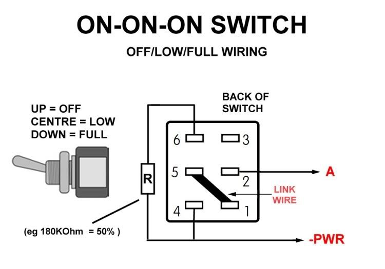
I’ve found what looks like a DPDT (Double Pole – Double Throw) 3 position toggle switch that operates like the one above but allows you to do off/low/high (or off/med/full … or whatever you want to call it!)
It is physically the same size as the DPDT switches that BCT supplied to some builders and the rubber boot that BCT gets from Rapid Electronics fit perfectly (it’s 6mm – not the same as Maplin switches or boots)
It’s a very clever (odd!) switch that requires a solder link between two of the pins for it to work as a true SPDT on-on-on switch (Yep, not a typo! A DPDT that acts like a SPDT with true on-on-on function).
Here is how you wire it for a simple off/low/full set-up …………
Here is how you wire it for a low/med/full set-up (provide your own separate on/off switch for no light!)
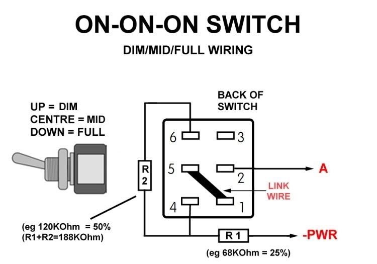
I’ve fully tested the diagrams with the switches and they work perfectly …. you just need to pick the resistors to set what levels you want.
Please note that trying these wiring diagrams with the switches BCT supplied or Maplin/Farnell/Rapid/RS etc etc switches WILL NOT work …. you have to use one of these on-on-on switch types that I’ll show the source of below!
Remember, the switches are the same size as a DPDT switch, i.e a little wider than the SPDT switch that Troutie shows on Page 2, or CK shows on Page 13 …. they look like this … except the ones I got are black! They have a 3A 250VAC / 6A 125VAC rating.

I got mine here, 6 off. They are also available here singly, and I think Farnell and other big suppliers have them too. One thing to note ……. buying them from other suppliers might mean that the important solder link position might be on different pins. My suggested suppliers send diagrams with their switches …no doubt the big suppliers have info on them too.
Hope this helps someone …. apart from me!
XyleneFree MemberPosted 14 years agoI have managed to buy the wrong Hammond box somehow, not sure how, but I have the solid plastic end pieced one, not the one in two parts with plate at the end.
thesurfbusFree MemberPosted 14 years agoQuirrel – you don’t need the box with the two part plates, it works just fine without them, and as there are less parts, less waterproofing is required.
You will have to drill two large holes (approx 20mm) in one of the end plates and fit the lexan behind, but I think this is a neater solution.
If you search through the posts there are plenty of pictures.XyleneFree MemberPosted 14 years agoI picked up a fancy drill bit at Aldi tonight, so should do the job.
bobblehatFree MemberPosted 14 years agoNo piece of scrap will be safe in Quirrel’s house tonight ……
Newwww Drilllllllll Biiiiiitttttt …….. Yeeeeaaaahhhh! 😀
XyleneFree MemberPosted 14 years agoIt’s one of thise different depth bits that you can use on metal. Shaped like a christmas tree. On sale for 4.99 three separate bits, seemed too good a bargain to leave
bobblehatFree MemberPosted 14 years agoQuirrel …. If it doesn’t give a nice smooth finish to the holes in the plastic front, wrap a bit of wet’n’dry around a suitable diameter round pole and finish it off by hand. It’ll look neat then. Good luck, and keep posting progress.
Here’s my test set up with a temp bracket to determine the angle between the high beam and the dip. It’s thin ali, so easy to bend. When it’s had a few test rides and I’ve tweaked the angle, I’ll make a thicker version and anodize it to match the black Kraken.
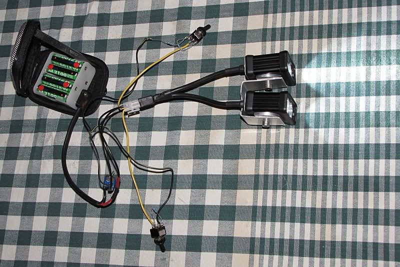
The new switches are working great. One is set up for 25%/50%/100% and the other for OFF/33%/100%, for testing purposes.
thesurfbusFree MemberPosted 14 years agoQuirrel – I paid £20 for one of those drill bits from Machine Mart, and also £70 for a pillar drill and £30 for a new soldering iron, so my lights haven’t been cheap.
flickerFree MemberPosted 14 years agoNice wiring diagrams Jay and Bobblehat 😀
I’ve finally powered up my lights today, all working nicely with the lo/hi/med switch and seperate power switch. I was originally going to build my battery pack into a water bottle, but saw this the other day which might be more convenient.
might get one on order this week and have a play.
flicker
troutFree MemberPosted 14 years agolooks pretty good that bag. will it fit at the other end near the seat post
to keep the front end nice and light.thesurfbusFree MemberPosted 14 years agoDoes the BCT Driver go into flash mode once the voltage of the battery drops off? Mine certainly did last night, my 14.8V battery pack was reading just over 6V when I got home.
Kev79Free MemberPosted 14 years agoHas anyone looked at these new XM-L led’s? I was toying with build a triple version for my bars, possibly using this new led. Just need to find a suitable lens/reflector for a nice floor beam.
I guess I would also need a different driver which is able to supply a higher current?
Cheers
bobblehatFree MemberPosted 14 years agoOne of my light heads did do some sort of flashy thing on one test when I accidently let my 8 cell NiMH pack run down to about 6V …… not recommended 😳
I think letting a 14.8V pack go down to 6V is a definite no-no too! 😥
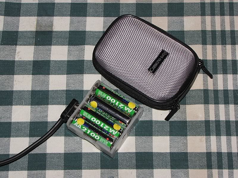
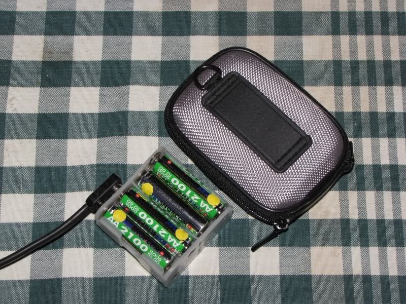
I went for a cheap option ….. a cheapy camera bag from one of those Poundylandy/worldy/savey stores ….. (Guess how much it was 😈 ….. but don’t ask the shop assistant if you don’t want a short rude answer 😆
It seems to have some hard shell inside that should be pretty weather resistant. A loop of doublesided velcro strap through the belt strap and it goes on the stem.
 XyleneFree MemberPosted 14 years ago
Quirrel – I paid £20 for one of those drill bits from Machine Mart, and also £70 for a pillar drill and £30 for a new soldering iron, so my lights haven’t been cheap.
Bargain then getting my drill bits for a fiver. Soldering iron was in the loft and my drill, well lets just say that a few beers numbs the pain when stabbing oneself in the knee with a drill. My body is the pillar.
I borrowed a 9v battery power supply from work.
I just spotted some 10 quid 18v drills at Netto tonight, so I might buy one for the house anyway and if it works then get another for the battery pack.
flickerFree MemberPosted 14 years agoMr T…. I can’t see why the bag couldn’t be used at the other end of the top tube, against the seat post. Found them for £11.99 at CRC too. Order going in tonight, will report back when it arrives.
BlackCatTechFree MemberPosted 14 years agosurfbus – I’m guessing this is 4x protected lithium? I’d suspect that what is happening is that the over-discharge protection is kicking in, turning the output off. The cell is then recovering when the load is removed and the protection turns off. As soon as the load is reconnected the voltage drops again and the cycle repeats.
The other option I’ve seen once is if the driver gets really hot it cuts in and out very quickly. Either way, I’d say this is not a recommended situation….
Kev – Maybe strap a generator on your pannier and just connect up a couple of 500W floods? 🙂
(3A drivers aren’t in my plans at the moment BTW)
troutFree MemberPosted 14 years agokeV
XML looks good. BUT
there are no tried and tested optics optics yet. and not a lot of the LEDs around yetI am usually quick to get the new LEDs. but am hanging fire this time and watch what happens on the optic front
it will most likely be a flood monster as it is a bigger die than the xpg. so small optic/reflectors will not be too good
drivers exist. that will power it. same as the mce. p 7 s
thesurfbusFree MemberPosted 14 years agoBCT – Yes it was 4x protected lithium batteries, the case wasn’t hot so don’t think the driver would have overheated.
It wasn’t planned to run the batteries so low, but when you are in the middle of nowhere in the dark, you need to get home. I thought I would have got a longer run time from the battery, but when I started to think the amount of times I tested the light in the back garden and then took the dog for a long walk, it makes sense they didn’t last aas long as expected.Has anyone been sent any Spam e-mails from someone in China trying to sell you LEDs and drivers? This is the only place on the web that I have discussed LEDs, so seems a bit of a coincidence.
philbrFree MemberPosted 14 years agoTrout
I appreciate I am a bit late getting in here, but do you have any XPG LED’s and regina reflectors still for purchase, ideally 4 of each.
CheersBCT
YGMbobblehatFree MemberPosted 14 years agoHey Surfbus …. no one offering me LEDs via spam …….. but plenty of spam offering to enhance my manhood …..even though I don’t remember discussing it here! 🙄
Sadly, none of the treatments have worked yet 😥
XyleneFree MemberPosted 14 years agoIt would be nice if somebody that understood all the jargon etc went through the thread and linked to key pages of info that others would find useful.
I am still at a loss as to how to glue the reflectors in place.
bobblehatFree MemberPosted 14 years agoPage 2 – Troutie does a good build up set of photos ….. still valid even if you aren’t doing a battery inside build.
No glue (although you could use AAA) … see Troutie’s pics of copper slip and screws. I used heatsink paste instead of copper slip …. no huge difference, I just had some.
Plenty of other photos of builds to look at ….. doesn’t take that long to scroll through the pages.
bigjimFull MemberPosted 14 years agoIt tells you what to do on the second page, or you can use some cunning and drill your led stars to take the holes. I nearly did but thought I’d just make a terrible mess…
troutFree MemberPosted 14 years agoPhilbr
Yep got plenty are you wanting the heat sinks and other bits and pieces too .I know it is a little late but now I am drilling the stars for the Regina now I have a little jig made up still need some glue though
but lots easier to dophilbrFree MemberPosted 14 years agotrout,
That would be great getting the heatsink, etc, and if it includes the polycarb for a bit extra funding, even better.
Could you let me know how much I’d owe.XyleneFree MemberPosted 14 years agoJust found a PC heat sink upstairs that will need a trim but might work to mount the LED’s to for more efficient cooling
GarySFree MemberPosted 14 years agoJust back in from a little night ride, the triple wasnt damaged after my last battery died thankfully. I am now running 4x ultrafire 3600mah batteries from a different supplier and they lasted 1 hour 50min on full. Pretty happy with that.
bobblehatFree MemberPosted 14 years agoQuirrel …. you’ve got to do some research and study this thread in detail. All the info is there if you look.
Troutie page 23 – their will be no usfull reason to use a finned or needle computor heat sink inside the housing as you need to get the heat to the outside as fast as poss .
if using the hammond case then try and find some U channel that is a nice tight fit and you would then need to add extra sinks to the outside of the hammond.
and ……..
BCT page 23 – Kev – as Troutie says, no use having the heatsink inside the box as you just heat up the air inside. Attaching one to the outside would be very useful though – fins and pins increase the surface area drastically and are especially useful when moving. Use a good thick piece of alu inside to get the heat away from the LEDs and to the case.
Do you have the piece of L angle that Troutie supplies in his kit? If yes, use it. If no, email me with your postal addy and I’ll send you a piece of aluminium channel that will fit nicely …. you can see it in my photos if you look back.
Use your PC heatsink on the outside if you think your case is getting too hot …… which it shouldn’t while you’re on the move.
XyleneFree MemberPosted 14 years agoyou’ve got to do some research and study this thread in detail. All the info is there if you look.
Have done, several times, saw the drilling stars bit when I first got the kit ordered on the third page…yes I have taken this long to get this far with it.
Decided not to drill the stars, due to not having a press.
Yes have the piece of alu, but thought looking at the case shape and the l shaped bit I would be able to add extra cooling with the heatsink cut and stuck in place, however being a spoon, I didn’t think about it being locked inside the case without air flow.
Everything else is pretty much clear.
I managed to lose bits of the kit from a sealed box before I even got around to starting on it. No idea where or how they got out, but the switch, cover, and one bit of wire vanished. They were 100% there before I started as well.
Still have no idea what way round the jack goes for positive and negative, but will dig out a multimeter from the supplies cupboard at work to find out.
I bought a cheap 10 quid drill at Netto today. I had planned to use the battery pack from it, it’s 18V but only 1000mAh so I will keep it for electric screw driving ability.
XyleneFree MemberPosted 14 years agoJust realised where I’ve been going wrong.
Been reading AAA as arctic silver paste that one would use with a pc heatsink, not the actual adhesive.
The topic ‘DIy 700 lumen batteries inside light’ is closed to new replies.

