So some of you may remember me as the hooligan who [url= http://singletrackworld.com/forum/topic/homemade-carbon-xc-frame-pics-and-details-as-promised ]built a carbon xc frame in my garage[/url] - but now I fancy a new project, and in one of those how hard can it be moments I decided I would give an XC full suspension frame a go, as I have aspirations of competing in the BC bike race sometime in the next few years, and fancy something a bit more comfortable for long/marathon races.
The aim for this bike is for it to be built up with 26 inch wheels for the time being, but in the future be able to change either the shock mounting point, a linkage or some other method to turn it into a 650b machine. (the arms will be built with enough clearance to start with)
I'm aiming for 90-100mm rear travel, a almost hardtail feel when locked out and not too many linkages, I would also like it to be reasonably efficient when not locked out too. It must also contain NO sections where it relies on the carbon flexing to give it the travel (so no scalpel-esk designs) I would also like front triangle based design for simplicity - as monocoques are quite tricky to home jig!
The current design I'm liking is something like the rocky mountain element - as it seems to get good reviews as being fast and efficient. Does anyone have any feedback they can give me one what works/doesn't work with this design - and where they crack/fail (if it's a common problem)
[img]  [/img]
[img]  [/img]
Does anyone on here know of any suspension linkage design software (preferably open source/free, or at least free to me 😉 ), or have any experience they would be willing to share with me on the art of suspension design?
Also - if you want to sketch any designs feel free to post them up yourself or either email them to me to post anonymously (if your drawing is that bad I may resketch if you ask nicely) for critique.
search for linkage for suspension design, there is a free version around not sure how much you can do with it though.
The element is a very good bike from the owners I know, not heard or seen of any cracking or failing on them.
and if you combine the answers to a design my bike you will get a 62 degree HA bike with 100-170mm of travel that is rigid with 26/650/29" wheels and fat compatible with a 1xSingleSpeed drivetrain and narrow wide drop bars 😉
hence why I felt I needed a few criteria that it needed to meet!
http://www.bikechecker.com/buy.php
This is the linkage place, they seem to have a RM Element in the library.
There is a free demo and it's $25 for personal use so not the worst price in the world.
You're mad. This needs to be kept updated!
What sort of time frame are you looking at?
I know a website with some useful piecharts....
😈
Having a quick play on the demo - if I give the project a go ahead then I will definitely be buying it - seems to work quite nicely so will give it a proper look when have some time! - as for timeframe - idealy get the brunt of the built done over easter break, as long as I'm not working that is - but I m then probably over the summer holidays and into next year
Do you have a background in carbon fibre or design or is it just something you thought can't be that hard?
As above Im looking forward to the updates.
damascus - no background in CF ( but I am an automotive engineering student) -I did a school project where I was donated rather a large amount of CF fabric (I only needed about 50cm^2), so I decided to do a project (the XC frame), and have now got hooked on making my own bikes! - and want a full suss. I always use the moto "how hard can it be" - and normally I find out that it's easier that I thought it would be (with plenty of research)
as for the linkage software - got some nice results just from putting in some rough numbers
[img] 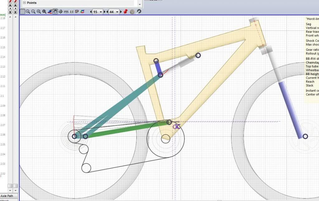 [/img]
You'd get much better help on one of the frame building forums
ok thanks for the advise - to be honest I hadn't even thought about looking for a dedicated forum! - off I tootle 😀
I'm still interested in the opinion of STW as all I'm trying to get from here is what full suss geometry people feel is best for XC racing.
So decided to put a build blog together for this frame as I had quite a bit of demand to document the last project - I think it will be easy just to do another project and take photos of this one!
Post 1 here - [url= http://bike-related-projects-and-antics.blogspot.co.uk/2014/01/project-2-in-pipelines-full-suspension.html ]Post 1 - designing the full sus![/url]
General blog here - [url= http://bike-related-projects-and-antics.blogspot.co.uk/ ]Blog[/url]
Interesting stuff.
Just one thing though, the design on your blog shows a 'faux bar' - eg a linkage activated shock on a single pivot swingarm, not a 'four bar (which requires a pivot between the swingarm and dropout)
[img] 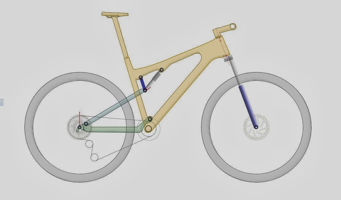 [/img]
ah ok - I was just going from what the Linkage X3 software called a "4 bar" - will edit that now 🙂
oops - double post 😳
Brilliant stuff.
Faux or 4-bar Horst link, actually makes little odds on a 100mm bike imo. I'd go for the ease of manufacturing if there's any difference there. Minor effect on braking between the 2, if anything I prefer a faux/single pivot overall for that kind of bike as I like the pedalling feel. The SP Element was one of my fave bikes of that era, really great XC distance bike.
Best compromise I've used/ridden is the axle pivot, SP pedalling feel with projected brake pivot ability, and since you're not going to get cease-and-desists you're free to use it..
Faux or 4-bar Horst link, actually makes little odds on a 100mm bike imo
+1
My favourite bike (so far!) has been a 2003 RM Element which was a single pivot.
That Element was always one of the German mags' most efficient in tests as I remember. I was a bit sceptical of the low, behind-BB pivot but it rode superbly.
I used that linkage software when I designed mine, was very useful. I ended up with something like the Whyte suspension.
I also researched how different suspension systems were reviewed in the bike mags. There was nothing consistent, lots of completely different systems, all got 10/10. Anyone would think bike reviews in mags were written to get advertising.
From what I've seen/ridden/read/believed the single significant factor for short travel is main pivot height (bar changing progressiveness significantly with a linkage etc).
If you build a four bar Specialized will sue your ass
If you build a four bar Specialized will sue your ass
Only if you make money from it.
And only if you sell it in the US (and maybe other places with silly patent laws but you'd be fine in Europe).
😯 so there goes the idea of shipping these off to america to sell them 🙄
The main reason I have ended up with this linkage design is the donor bike, and how it's dropouts are designed, I also feel that I will be able to modify the bikes travel easier by swapping out the seatstays and linkage should I need a longer/shorter travel bike temporarily 😛 - As for efficiency I would like it to minimise pedal bob as much as possible, so the higher front pivot. I'm planning on using a monarch xx (unless someone is selling a fox rp23 or monarch rc3 cheap) rear shock so will have the remote lockout for sprinting so don't mind a little bob.
I had a remote lockout on the rear of my RM Element and it was brilliant - flick of a switch and you're riding a bike that's like a rocket up the smoother stuff.
I hadn't realised quite how tricky it is to get hold of a decent remote lockout shock! - looks like a monarch XX really is my only option! (not that that's a bad thing)
Due to a request I have done another update with a few more intricate details on the design and the CAD work I have done - [url= http://bike-related-projects-and-antics.blogspot.co.uk/2014/01/project-2-part-2-more-designs-by-request.html ]Part 2 - more info by request[/url]
Looking good. You should think about how everything is going to be aligned as you build it. I made the swinging arm and the mounting points on the frame separately, then built it into the frame. Don't forget you can't cold set a carbon frame like you can steel.
Edit, and the green links in your design, are they going to be stiff enough?
The plan is to get some mdf and drill holes exactly where all the pivots and major points will be as coordinates are provided by the linkage software, and then get some pieces of 2by2 with perfectly aligned holes at 90 degrees to the mdf to hold 30cm ish arms to hold the bike with a centerline on a virtual plain 30cm from the mdf (how I built the hardtail) - but I plan on making the swingarm and chainstays in a separate jig, but testing them for fit after the first layer of carbon so they can be modified if needed!
I will do photos when I have made the jig, but a quick mockup of it in the CAD model looked promising - but I forgot to save it!
EDIT - the green links are just a mockup - I plan on using two aluminium 8mm sheets 25mm wide with holes in - but not to the extent of the CAD - I also plan on linking them together with a machined piece of aluminium (or just use carbon fibre to link them if I can't be bothered to machine it!)
Sounds good, I used some Al extrusion for my jig:
[img]  [/img]
I'll admit I have had a good look at your build photos - and I almost went for a similar jig for the hardtail last summer - but I found the mdf method fine (or better way of putting it - cheap 😉 ), because once I added the first 2 layers of carbon I found it was easier to lay up out of the jig as I could rotate it 360 degrees to get to all the tricky bits!
Yes, MDF will be fine, I only used the Al because I had some I got for free.
Next update - the building begins! I started the making the small parts, and should hopefully get the jig and the front triangle assembled by tomorrow - and will update ASAP! 
[url= http://bike-related-projects-and-antics.blogspot.co.uk/2014/01/full-suspension-frame-part-3-building.html ]Here :lol:[/url]
Update number 4 for all those who are interested, I have managed to get the jig built and the front triangle loosely put together in it!
[url= http://bike-related-projects-and-antics.blogspot.co.uk/2014/01/full-suspension-frame-part-4-jig-core.html ]Part 4 - The Jig, The core and putting it together![/url]
Really enjoying this thread, good effort!
Part 5..... [url= http://bike-related-projects-and-antics.blogspot.co.uk/2014/02/full-suspension-frame-part-5-adding.html ]Here :D[/url]
I have now added the main pivot mount and a few more layers of carbon elsewhere
Part 6... [url= http://bike-related-projects-and-antics.blogspot.co.uk/2014/02/full-suspension-frame-part-6-making.html ]Here :D[/url]
Sadly this will be the last update for a while, I may do some small updates should I have time, but its unlikely I'll get round to much till late march.
Looking good mate!
thanks - just really wanting to get it finished but going to have to wait till easter!