Carrying on from my latest [url= http://singletrackworld.com/forum/topic/like-a-fargo-but-carbon-design-a-bike-for-me-2 ]design a bike for me thread[/url], I've started building the frame. I have decided to go for 29er wheels (and not bothering with 27.5+), and similarish geometry to the fargo, although I will be steepening the head angle a little bit (0.5-0.75deg), while shortening the stays a by about 8mm.
As some of you may remember, I have been keeping the insulation tape industry alive with some of my [url= http://bike-related-projects-and-antics.blogspot.co.uk/2014/01/full-suspension-frame-part-4-jig-core.html ]past frames[/url], so for this build I decided to splash out and get some (marginally) better equipment. Those that know their Tupperware catalog, will spot that what I'm using as the catch pot and pump is a Vacuvin coffee storage container, which can easily reach 27inHg of vacuum, so perfectly adequate for resin infusion.
[img] 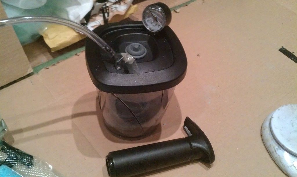 [/img]
I have tarted the CAD up a bit to help visualize how it will all look together (I wont be running a -17 degree stem, that was just to see what my range of adjustment would be). By my calculations a -6deg 90mm stem should be about right and is what I have in the spares box.
[img] 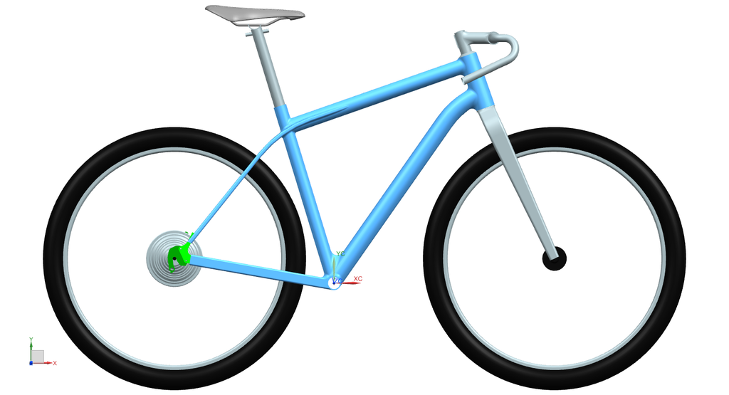 [/img]
I've had some dropouts cut (about 5 sets it total; 3 geared, 2 ss) so all my future builds should be able to be interchangeable (No I will not be going boost 148)
[img] 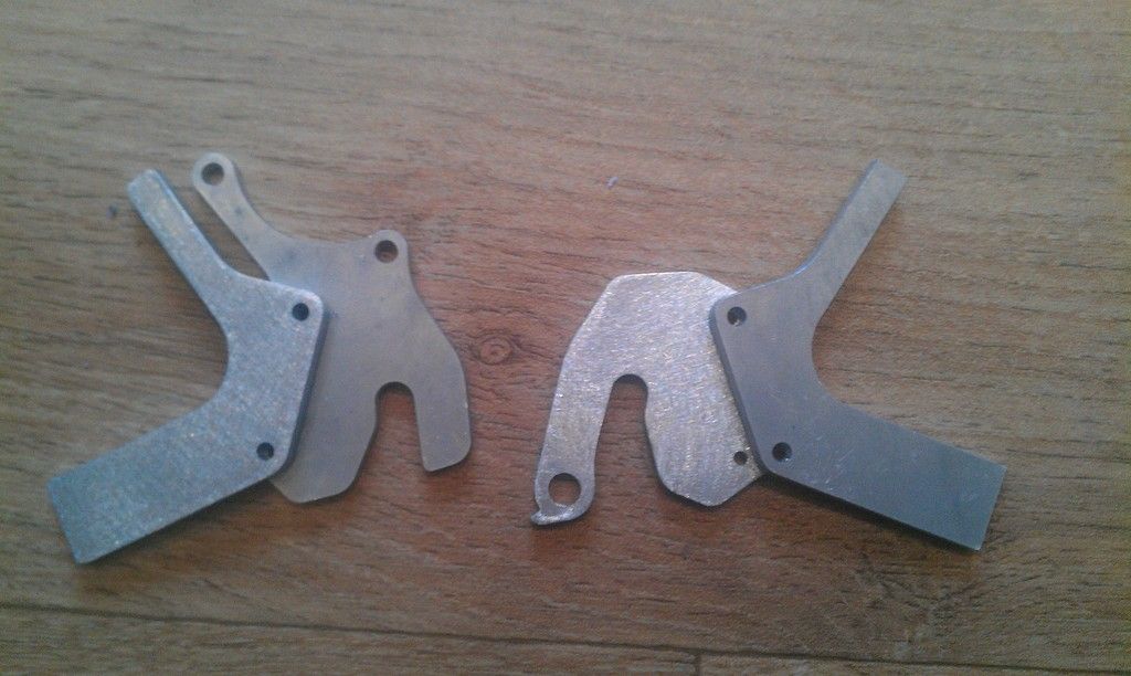 [/img]
For the smaller tubes (seat and chainstays) I'm first fibreglassing them to increase their rigidity before cutting the centers out, as I had problems with the past 2 frames of the foam cores snapping.
[img] 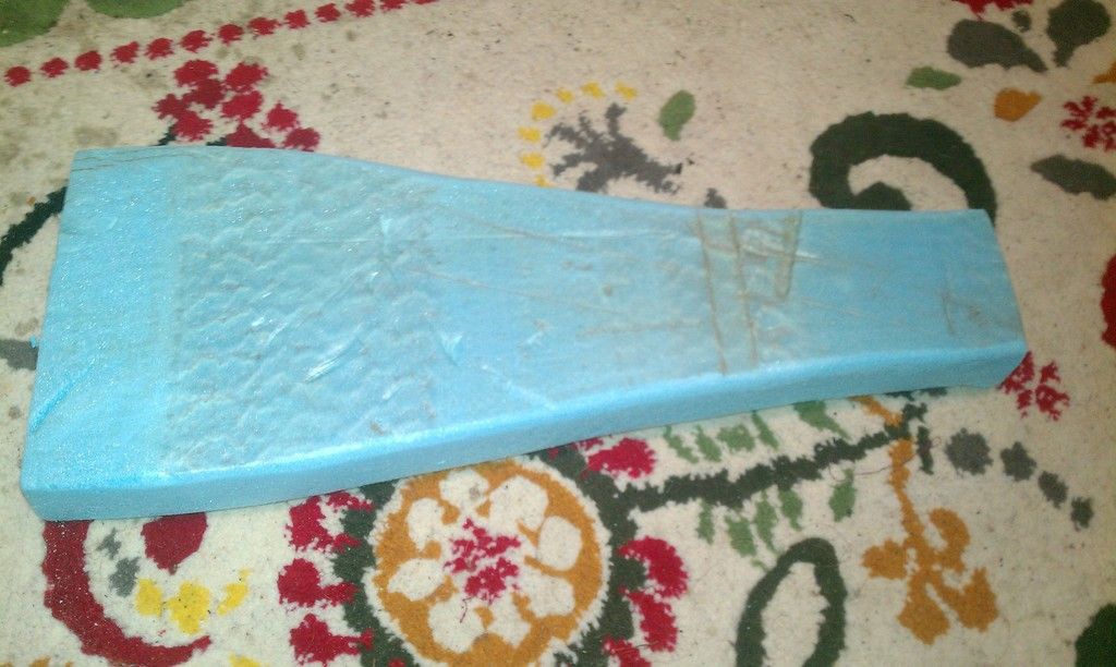 [/img]
[img] 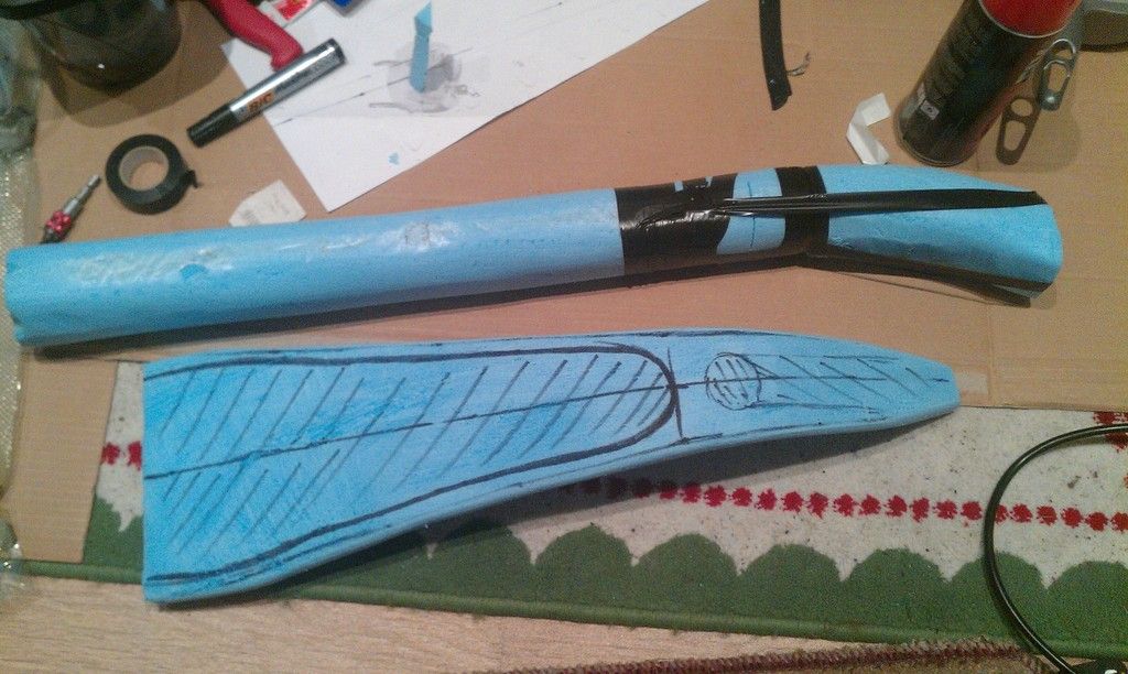 [/img]
[img] 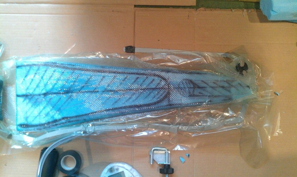 [/img]
[img] 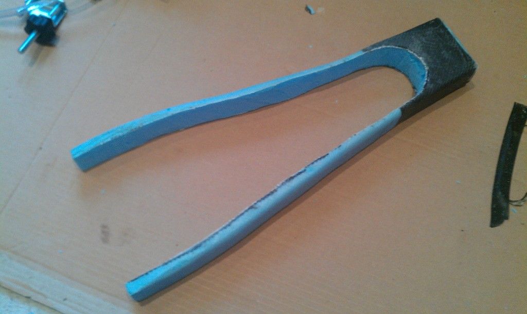 [/img]
I'm still slightly undecided on how thick to make the downtube, I'm airing towards a 60 wide, 50mm deep oval (the full suss was 75-60mm oval)
[img]  [/img]
This is gonna be good. Bookmarked for reference.
Best of luck
Loving the look of that seatstay/seatpost join, bookmarking here too.
I would go for the biggest/stiffest down tube that looks ok, especially if your going to be bike packing with loads. Is it going to be able to take a tapered steerer?
I admire your attitude. Will watch with interest!
Bets on which country he'll inevitably eject his bb in anyone? I'm disappointed at your lack of wood used in this project!
Not going to happen! 😉Bets on which country he'll inevitably eject his bb in anyone?
Yep, tapered steerer with drop in bearings so hopefully as low maintenance and as simple as possible, I'm using the same method as the the full suss frame I built last year.Is it going to be able to take a tapered steerer?
Brilliant work - looking forward to watching this develop.
Any new ideas to improve on the previous bonding / galvanic issues?
Please tell me you're not making the fork 🙂
Fabulous! Good luck chap
Tupperware? Not even [s]Spoonman[/s] Cynic-al would have dreamt of such a thing!
Love it!
Bookmarked as I'm about to embark on a similar project
Watching with interest as well.
What size bolts are you going for with your swap out drop outs?
You going for a fully integrated headset?
Tick.
this is brilliant. Love garage manufacturing.
What size bolts are you going for with your swap out drop outs?
Lots seem to use chainring bolts FWIW.
I love this kind of project, please keep updating this thread.
What size bolts are you going for with your swap out drop outs?
2xM6 per side, I'll tap a thread into the removeable dropout, I'm actually using the same design as a 1995 Giant cadex, which is what my 1st frames dropouts were nicked from, and it worked for them so I thought I'd give it a go!
You going for a fully integrated headset?
Yep, drop in bearings as I did on the full suss frame last year.
I should hopefully have a few more updates later today, I've built the wheels (crests on SP-PD8 and 135qr rear hub), forks are in the post, as is the headset!
Any new ideas to improve on the previous bonding / galvanic issues?
No idea what the problems were but guessing aluminium inserts (eg BB). Normally you would wrap them in a few layers of glass and epoxy first to create a barrier between the carbon and aluminium.
edit: just spotted the aluminium drop outs - again you would wrap these first with glass and epoxy and then bond to that with the carbon.
The Identiti bikes used 2x M6 bolts for there ADS system and it seemed to work pretty well. It must just be the picture as the holes look a lot smaller than M6.
Intrigued as to how you will do the head tube. Looking forwards to more pics as they come.
Loving that Vacuvin btw. Looks perfect. Have you got a catch bag in there with breather so you don't trash it?
I have to say watching DIY carbon bikes reminds me of how much less landfill waste metal bike produce 🙁
Yep, almost all the joins I've done with this method have been ok, but the two that I forgot to do it have failed , so will definitely be doing this for all carbon/metal joinsfew layers of glass and epoxy first to create a barrier between the carbon and aluminium.
Yep, I got them done at 4.5mm so I had room to drill should the precision of the laser cutting be worse than advertised. it actually looks like they are about 5mm so I'm glad I left some room to spare!the holes look a lot smaller than M6.
You'll see shortly...Intrigued as to how you will do the head tube.
Yep, it's likely still gonna get trashed, but I'm using a small pot in it to catch the main stuff and putting some breather cloth around it to catch any drips.Have you got a catch bag in there with breather so you don't trash it?
Does your vacuum method mean that it's going to be slightly more appealing to look at or is it still going to be oli-chic like the others?
The Identiti bikes used 2x M6 bolts for there ADS system and it seemed to work pretty well. It must just be the picture as the holes look a lot smaller than M6.
the ads system and most sliders bolt in between two ledges on a rail so that their is a mechanical joint and the bolts are not working in shear. might be worth bumping up those hole sizes to account for this.
Yeah I did think about making the bolts bigger, but the Cadex that I've borrowed the design from has been ok for 20+ years (and is just a flat plate to a flat plate), I'll see how it goes but I've done some pen and paper calcs which suggested even an m5 would be ok ( assuming a 1m Drop to flat with a 100kg rider and no flex from the tyres), so a m6 being about 45% stronger should be fine.
Nathan - I hope so, but tbh it's a bit of an experiment but so far it's been easier to make nicer looking tubes as long an I'm careful with the layup.
So forks arrived today, the look great and have allowed me to start my headtube. I am using the steerer as a partial jig with a 5mm layer of foam taped over to allow it to be as thin as possible. The headtube is 16cm high, but only has about 5mm of added stack from the top cap. I have gone back to wrapping with electrical tape rather than vacuum bagging due to using the fork as a jig.
[img] 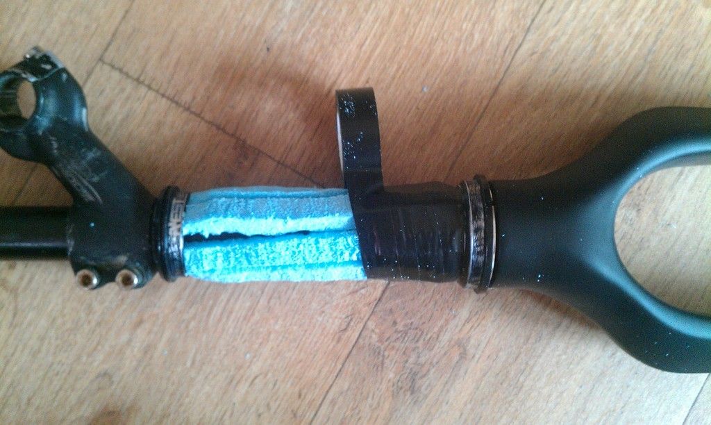 [/img]
[img] 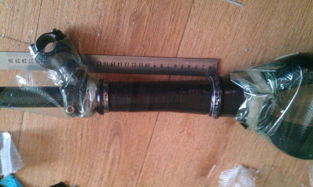 [/img]
I have positioned the tubes roughly how they will fit on the bike. All tubes are quite a bit longer than they will be so they can be cut down. I'm still undecided on how big to make the downtube although I'll likely keep it pretty similar to how it is now.
[img] 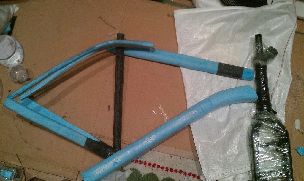 [/img]
Bookmarked. Ace project!
Very cool, cheers for sharing!
Oooo that's an interesting way of doing the head tube, I had kind of thought you would be dressing a steel head tube into your carbon frame.
Keep up the good work.
Fair play, looking forward to seeing the end result.
It looks to have a very short wheelbase, are you going to have any toe over-lap?
love these type of projects. way above what i can do just now stripping motorbike carbs and doing valves etc about the height of my achievements so far...
Brilliant! keep this updated please!
So, didn't get much done over the weekend as was helping run a sportive, but I have now got the preliminary shape of the headtube made, but I will build up about 6 more layers. The bottom bracket now has 5 layers, so needs another 3 or 4. I have also tapped the threads into one of the sets of dropouts, so I could assemble to test the fit.
[img] 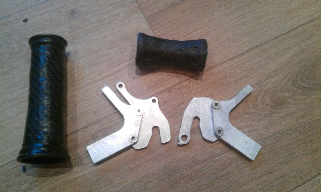 [/img]
Behind the scenes I now have the wheels and most of the finishing kit sorted, but still need to source a rear mech and either a set of 10 speed STI levers or a 10 speed bar end shifter. ([url= http://singletrackworld.com/forum/topic/wtd-9-speed-xtxtr-rear-mech-and-10-speed-road-shifters-bar-end-or-sti ]See wanted thread here[/url])
It looks to have a very short wheelbase, are you going to have any toe over-lap?
I have done some quick estimates, with a 2.2 tyre and 175mm cranks running the shoe/pedal setup I do I should have 5mm gap, so hopefully not, but it wont be a huge issue if I do as I'm used to riding a cross bike with tonnes of overlap!
Looks good! I can't wait to see it coming together, although it looks like your headtube is much smaller than the tubes that attach to it, it this how it is or a trick of the camera?
The dropouts look very thin around the bolts, or is it just a that the bolts have big head on them?
After a couple of days of not being able to do any work on it I have started laying the carbon for the tubes. I have opted to go for the large sized down and top tubes, partly for added stiffness, but also as I plan on using frame bags with it so a larger tube should allow a thicker bag to be used.
[img] 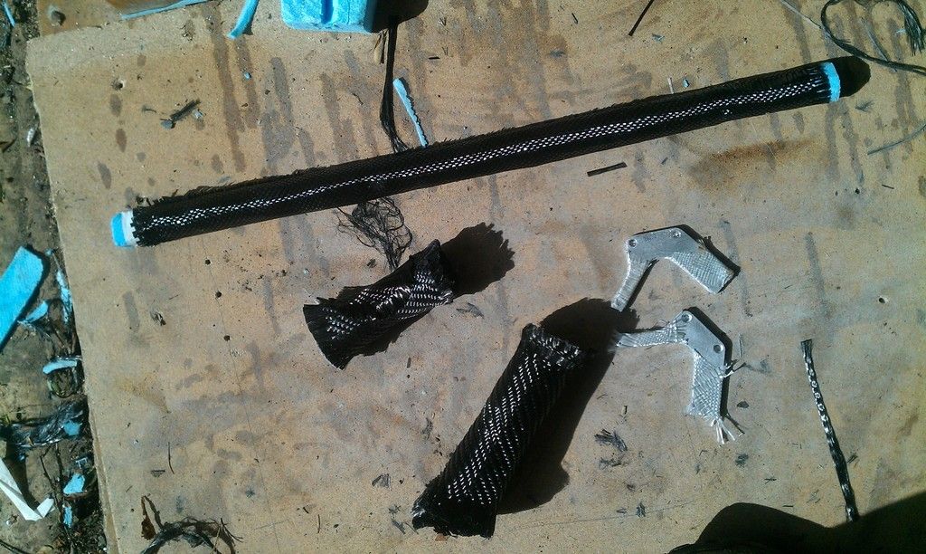 [/img]
[img] 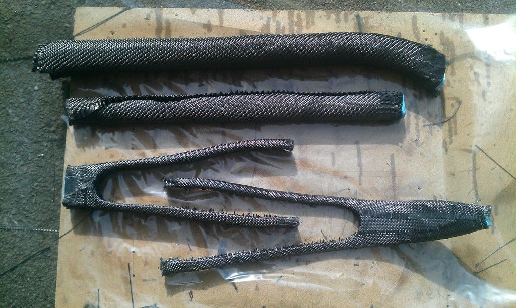 [/img]Using fine mist of Fusionfix spray adhesive it allows me to position the fabric how I want so it stays in place when the vacuum is drawn. The layer of fibreglass can be seen on the drop-outs as discussed earlier.
[img] 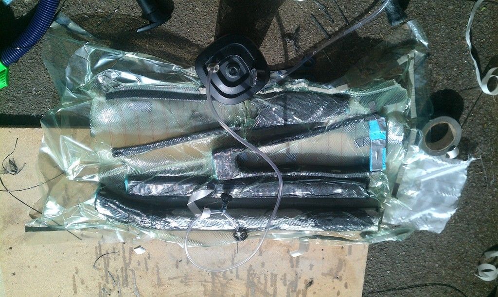 [/img] I put all the tubes in one bag to reduce the ammount of materials I using as much as possible.
[img] http://i1331.photobucket.com/albums/w593/oliverracing/IMAG1686_zpswhczaktf.jp g" target="_blank"> http://i1331.photobucket.com/albums/w593/oliverracing/IMAG1686_zpswhczaktf.jp g"/> [/img]
As I'm adding cage bosses onto the carbon forks I have added a couple of extra layers around where I'm planning on drilling.
The bolts do have a big head on them, and I plan on swapping them out for slightly longer ones as these only go half way through the dropouts. As for the headtube size, I need to add some more layers onto it, and the top tube tapers in slightly to meet it.
I've built a few frames in this way and ended up going back to the compression tape method (you know you can get some cloth tape with release agent built in? you get more resin release than with electrical tape). I found with the vacuum bag and the 'wet' layup material, I got loads of wrinkling that needed sanding out, breaking the fibre continuation and compromising the frame. It'll be good to see how you get on - your threads are inspiring me to pull my finger out and get on with some more projects/ideas...if only I had the time!
Yeah, I've found it to be much better than tape for the smaller tubes, but a few small wrinkles have formed on the larger tubes, I think it will also be better for the final assembly as I have found it difficult to get compression on some of more complex joins. For the rest of the build I'm probably going to use a hybrid of both methods.
I have used the compression tape but I find electrical tape more consistent. I may try it again now I have more experience.
As for time, the delights of 4 week holidays for students...
Bookmarked! Like the look of this build.
Yeah, the complex joints comment reminded me of a good idea I saw on that Magura 'home made' fat fork. You can use an old inner tube placed in the area, secure with tape (also stops it expanding in the wrong direction) and then inflating so that it puts pressure on the composite. Looks to work well on tricky concave junctions - not tried it myself though.
Yeah, I've used the inner tube method on a mudguard I made, but I don't think it would work too well for some tube more complex/larger joins (unless you use a very lightweight fat bike tube)
follow
Watching with interest....
So the build continues...
[img] 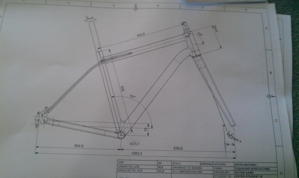 [/img] To get the geometry right I have fully dimensioned up the assembly drawing so I could really on measurements as well as angles.
[img] 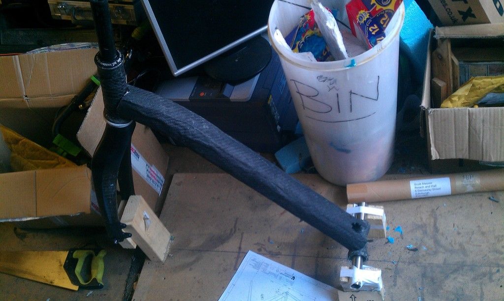 [/img] I built a jig to clamp the forks, bb and dropouts into, this seems to have worked pretty well. To start I placed the downtube in position and set in place with some rapid set epoxy.
[img] 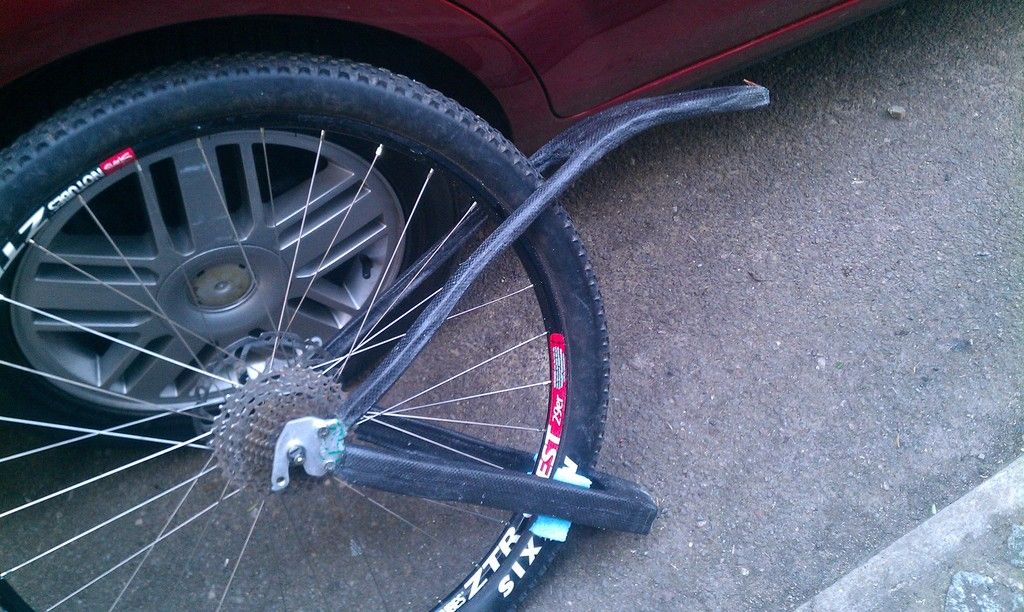 [/img] I also assembled the chainstays individually, so to make sure it was properly aligned with the rear wheel. (only chain-stays are gluing at this point)
[img] 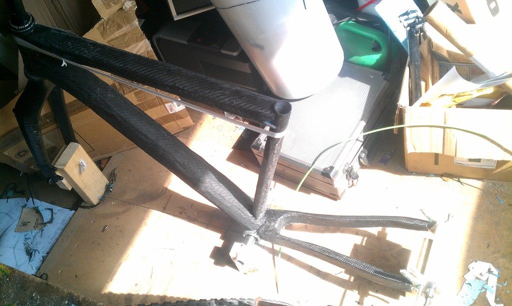 [/img] Top tube and seat tube were then attached, along with the chainstay/dropout section.
[img] 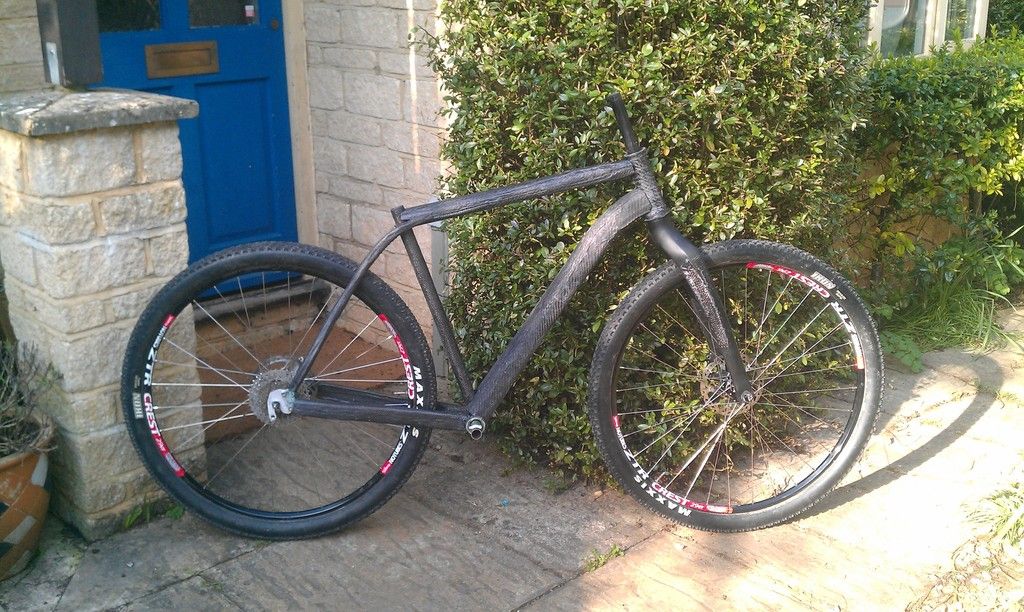 [/img] And finally the seatstays were added! I have double and triple checked all the geometry before adding the carbon reinforcement. 🙂
[img] 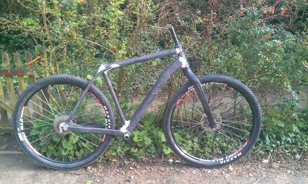 [/img] I have used some epoxy/glass bubble filler to smooth out all the joins.
[img] http://i1331.photobucket.com/albums/w593/oliverracing/IMAG1699_zpshic3eiqt.jp g" target="_blank"> http://i1331.photobucket.com/albums/w593/oliverracing/IMAG1699_zpshic3eiqt.jp g"/> [/img] The first layer of reinforcement is now added and curing ready for the final layer next week!
*LIKE*
Well done pal, genuinely great thread.
slight no pictures update... just gone to check on it and it turns out a single layer carbon tube can't survive a vacuum and has crushed flat in the middle. 😥 looks like I should be able to cut the middle/bad out and redo it, but still bloody annoying
^^^^ bummer. But it's all learning! Great effort so far, very impressed.