Jazid - the be fair, my problems with TCB seem to be mainly down to retailers not TCB themselves. However, they seem fairly toothless in resolving problems were the retailer decides they don't want to pay up.
Lipseal - you have mail.
sv - you'd better not! The only way to provide reverse polarity protection on the drivers would be to add a blocking diode which would gobble up another half a volt or so of your precious battery life.
This looks like a great little project, looks like I've arrived at the bar after last orders though!
Trout, is there any chance you'll be putting in another order to cutters in the near future or would you be able to post part nos. up so I could order the leds and reflectors myself?
BlackCatTech - TopCashBack so far have been [url= http://www.topcashback.co.uk/Blog/ ]very different[/url]!
We have therefore identified marketing budget which we can use in this instance, to make sure that none of our members lose out as a result of this affiliate network going into administration. In other words, where due you can expect your affected transactions to proceed through to Payable status as normal
I've just had the £18.75 through from the NationalTrust that has been on hold for ages and ii is now clear that it provided through the affliate DGM. I am so glad I moved away from cashbackkings and quidco.
As I said, if you use my [url= http://www.TopCashBack.co.uk/ref/Jazid ] link[/url] when signing up you'll get a £2.50 bonus.
got my BCT stuff too - thanks. gets really interesting now!
Cheers BCT all sorted now 😀
[IMG]  [/IMG]
Chinochio
I do have some extra on the order and of course want a few for myself
so will update when I have had a count up .
package status is - sorted in Hub as at 22.00 last night .
so looking like monday before I get them .
Address status
Vinnyeh
Wildrness
your addresses are required
Much appreciated, thank you Trout.
BCT thanks and also to Troutie for the wiring diagram! Soldering iron awaits 😉
...got my driver today, thanks BCT.
I've opted for the 3way switch route; I'd like to 'fashion' a thumb operated back-lit switch mounted ergonomically in Sugru (Trouties idea).
Does such a switch exist that would give on off dim (resistor in series on this line)...don't want a toggle version, I think the lupine lamps have this type of button switch?
On that note, have you guys seen the new Lupine PIKO? Nice unit.
Oh, can anyone confirm if the Lumicycle HID Li-on battery pack jack is centre neutral...I'm sure it is but just wanted to confirm.
Cheers.
A push-button switch would have to be latching to work with my (very basic!) driver. I don't know of any three-position push buttons. Most drivers which use push buttons have a microcontroller on board which registers the button presses and changes the operating mode as a result.
This would be a nicer solution but would about double the price of the driver and increase the size also.
Forgot to mention that two latching push buttons could be used, one for power and one for full / dim mode.
Not sure about sealed push buttons but if you look on Rapid they have toggle switches you can buy weatherproof covers for.
Thanks guys, will re-think it all 🙂
I have latching versions of the switch Trout and I like to use on our lights.
They have a built-in LED too.
Only issue could be current across the contacts.
BCT. Is the switch on its own low current circuit ?, or are you just interupting the battery cables ?.
Either way, contact rating for the latching apem switches I have is ~50ma, IIRC.
Potentially a daft question, but looking at some of the switch ratings I notice 220-240 volts. Do I take it that they can handle up to 240, but would alow anything up to that to pass through...they are not fitted with bandwidth type resistors are they??
I take it the switch takes power from the connection to illuminate?
Thanks Luminous,
The 'fried' driver that came with troutie little fickir (mini unit) had obvious switch terminals...which I kind of wish I'd gone for now. That said, the BCT driver is half the size!
From BCT wiring sketch I can have a switch(3way)with restistor on the low circuit loop, or a 2way that gives on/of without a dim option.
Cell lines go direct to terminals on the board.
Cheers.
Essentially, I'd like to have an illuminated switch on my index finger to activate using my thumb.....because I'm a geek before you ask 😆
LT.
I don't know enough about the BCT driver to issue a ruling.
All I know is that I've a few IP67 rated latching switches with in built LED.
Also, were you using a Taskled driver, then having an illuminated switch wouldn't be an issue, I could sort that easily.
Good luck.
😉
Becoming damn popular these lights now doing a high vis commuting
helmet light for a mate .
with built in back light
[IMG] 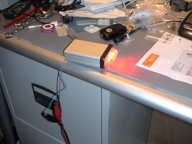 [/IMG]
[IMG] 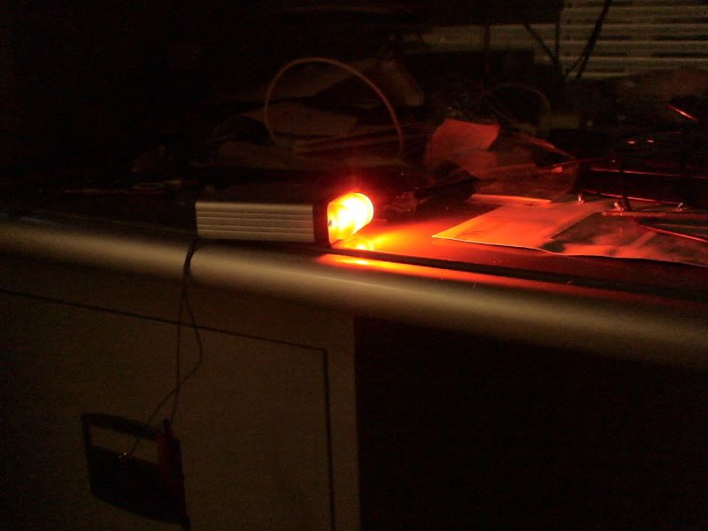 [/IMG]
Trout what did you use to insulate the heat sink from the terminals on the driver, as it must get hot and don't want to use something that might go on fire or melt.
Would it be secure enough to use thermal tape instead of screws/bolts to attach the led's to the heatsink?
Was going to glue it on, haven't noticed any holes to use a nut & bolt. Thermal tape may come lose if it's bouncing round?
Lipseal- if you look at the photos on page two of this thread, trout has used some screws to attach the led stars to the heatsink. Glue sounds like it may be a good idea and possibly stronger than tape. Can you get thermal transfer type glue?
trout would it be possible to build a unit that had a front and and rear light - would be ideal for helmet mounting?
steelfan thought you mention the heat sink. Yeah you can get thermal glue on eBay there's a link on here somewhere.
Gary that is what this one is going to be .
My Mate is always losing his tail lights so we figured with a combined unit fixed to his lid he would be safe with both lights .
and with it being high up and very bright with a 180 degree beam very noticable.
it will of course be switch offable as off road you would not want to follow it.
Lipseal .
there will be a small piece of flat ali in the kit which glues to the driver but not touching the contacts so leaving them isolated from the case
I have never used thermal tape so dont know how good it is .
but dont forget the reflector is also glued to the led board and you dont want anything moving .
holes and screws with thermal paste is the most eficient you can use small self tappers bolt and nuts or dril and tap the angle .
Copper slip is a good thermal paste not quite as good as the arctic silver but good enough for this job .
thermal epoxy glue is next in line for eficiency
and thermal tape botton in the heat transfer league table.
all are better than nothing .
there should not any burning hot things in there
Oh and another tried and tested thermal paste is Zinc and castor oil cream for the old saddle rash .
Sounds ideal trout, how difficult is the build compared to just a front light?
The switch connection I've recommended takes advantage of the low current (about 50uA) shutdown mode. Power is permanently connected and the switch simply operates on the shutdown control. Therefore an illuminated switch wouldn't work.
There is no reason you couldn't use one switch to interrupt the power and another to switch the resistor in and out of the control pin for full / dim mode. The power switch could be illuminated if you can find the appropriate type - most neon ones are configures for mains operation. Some LED ones are configured for a specific voltage, others are more flexible.
dead easy and lookin at mine which has 2 Xpe red leds you only need 1 led . a lower power driver 350 ma from BCT and on off switch and a piece of clear something to cover the red led up with
plenty of room in the hammond box for all the extra bits .
will do a few pics tomorrow while I am finishing it off.
Troutie - Simple way to do this if you have enough battery voltage is to wire a single red in series with the two whites. Have a switch which shorts across it to turn it off and job sorted.
One thing - wouldn't the white light be pointed slightly downwards so the red would have to be at a slight angle in relation to it. If you don't have reds that can take the same current you could wire a few in parallel.
The reds only need 2 volts and can handle 700 ma but are fooooking bright at that plenty bright enough at 350 ma
Are you lensing the reds or relying on the wide beam spread to maximise visibility? There are a few alternatives that run at lower current and you could use 2 or 3 with a linear driver such at the Infineon BCR450 for a simple and cheap solution. Running three at 100mA wouldn't even need much of a heatsink.
Hi Luminous,
Forgive my late reply; I don't yet fully understand the wranglings of the LED world, so pls explain the Tasked driver thing?
Also, I don't have much room (I renovating trouts micro..see this thread http://www.singletrackworld.com/forum/topic/calling-troutie ) inside the box for extra drivers and stuff.
The BCT driver is about half the size of the one shown in Trouts' picures of the unit.
How much would your solution set me back, and would you explain it via diagram pls.
Thanks for your help.
Oh, before I go....do you happen to know if the Lumicycle HID Li-ion packs are fitted with a centre-neutral jack...I'm almost certain they are?
PS: Thanks BCT (if ur reading this) for ur wiring diagram..very clear thx.
Oh, just one more thing.
A big thanks from me to all the folks on this thread for being good-eggs & sharing the LED love 😆
Free floor space and chocolate swirl cake if ur ever up the Peak way.
LT
PS: If you can handle the twins that is? 😯
LT.
Yes, lumicycle are centre negative, So just be careful with your case as you ground everything out with the screws etc but the socket should you use one will be positive ground for the lumicycle battery.
Hope that makes sense?
Lovetubs
that old driver was a Taskled Nflex and no longer in production .
I doubt you will get a Bflex in as they are 25 mm in diameter and have
components on both sides .
you would be best to stick with the bct and a sub miniature switch
the reds have a piece of half round acrylic rod over them which gives out a horisontal oval beam spread so is visible from a huge angle .
they are what i had but have in the past used 3 or 5 mm red leds in similar lights .with a resistor tapped in to the Bflex led output .
Thanks guys,,,
Smudge, could I not circumnavigate the inverse polarity simply by soldering the power lead from the battery poss to neg, and visa versa??
ASIDE
I don't want to hijack this tread, but I found this and thought you'd all appreciate it... I really must post up picks of my 1st dual lamps..
http://blog.makezine.com/archive/2006/12/how_to_make_the_ultimate_1.html
LT.
Yeah, I agree with Trout.
Stick with the original plan, and just go for the usual toggle switch. Keep it simple mate.
😉
Just thought I'd make it an even 400 posts 8)
Hi All ... 1st post here. Don't know if this schematic layout is of use to anyone (hope link works!) Feel free to comment on any aspect of the design or my queries in that thread. You'll see it's a twin system, separate on/off switch, 3 light levels for each light head with independent bar switches as crudely depicted in the animation/schematic.
http://forums.mtbr.com/showthread.php?t=657480
The table lets you work out various light levels (approx) for standard resistor values.
eg1 if you wanted 10%/FULL/50% then R1=22Kohm & R2= (200K -22K)=180Kohm approx.
eg2 if you want 70%/FULL/OFF then R1=470Kohm & R2=zero ohm (short).
As mentioned earlier, it is not possible to do OFF/X%/FULL using the ON/OFF/ON switch alone, extra circuit is needed.
Cheers, bobbl@
Cheers BTC I now have a some components to fry together 😳
bobblehat cool post but its a bit complicated for me think I will just see how things go with this build first an take it from there.
Very useful post, Bobblehat. One comment, output powers less than about 20-25% won't be possible as the driver will go in to shutdown. The actual shutdown point will vary slightly from one driver to another but the manufacturer quotes 25% on their datasheet as the 'maximum' point at which it will shut down.
(Will reply shortly regarding the extra driver, sorry for the delay!)
Luminous & Trout,
Agreed; will keep with original (simple) set up...so easy to drift onto the 'conceptualisation' track 😛
I maintain, however, that an illuminated switch for opposing thumb operation would have been the Dogs