Done three solders today....[url= http://www.aaroncake.net/electronics/solder.htm ]CLICK[/url] [url= http://www.ehow.com/how_4798949_check-bad-solder-joint.html ]CLICK [/url] for some help.
Thanks folks ... understand that most will want to keep it simple. I am trying to replace near like-for-like my old twin halogen set up which has been OK on and off-road for a few years. I thought I might as well take advantage of the superior dimming potential of Leds over Halogen while I was at it, especially since I am assuming that the Leds will be a good deal brighter and could be annoying at full power for on-road use. 8)
Thanks for the heads up on the lower limit BCT. It was just a theoretical table from a spreadsheet, so good to know that the lower values are a bit "too" theoretical! I'll amend my diagram in MTBR. With what you said, I might try a 25%/Full/50% to start with and if it proves a little OTT, I can easily use the same switches to go ... say 33%/Full/OFF and lose the ON/OFF near the battery. The Tamiya plug will be my hard-off in that case 😉
Also, I think Troutie is going to do me a swap with a used 970mA driver for my 8mm star xp-g's that I can't solder! 😳 No problem with delay ... you've got a lot of customers on here to keep very happy and if the swap-shop goes ahead, I apologise for the bad timing on my request. Funny the way things work out. I'll email you either way so you know if I still want one or not. Thanks.
This is my 1st Led build so it's bound to change design as more feedback comes from experienced builders and then from practical use of it. I suspect that the reginas might get swapped out on the dip beam (to what though?) ...but I'll give them a go first.
Ey up, (I'm taking an 'Up North' cse)
Forgive me bumping again, but still need a steer re- Lumi polarity. As the battery is centre negative....actually I'll redress the question. Can I assume that the socket I intend to use from the unit to the board will come with a split down diagram and thus I'll know which wire will be negative when I stick the battery male end into it? Then, surely, it'll be a simple case of soldering the appropriate polarities correctly?
Cheers guys.
Helmet light and tail light little vid
It may be a bit bright
Lovetubs
yes as far as I know all lumicycle stuff is wired arse about face .
Centre Negative.
so as long as you take this into account you will be OK .
if you are useing a lumy compatible socket the wire it the same but this does make the case live so be carefull not to have any shorts .
or you could make a crossover cable
Thanks troutie, why didn't I think of that...just buy a cable from LC 🙄
Hey, 'Double-Combo' is impressive, yet, it has nothing on your 'reverse with camphone skills'!
I was on the edge of my seat, waiting for the 'You've been Framed' bit 😆
How small could you make that rear light unit? That would be great if it could be attached to something like an under seat bag clip for easy fitting and removal.
Quirrel it could be made pretty small and use a PP9 rechargeable .
Good news the leds are last tracked at leeds and out for delivery .
the bad news is there will be no one home after 09.00 so may get taken back to the sorting office or put in my safe place fingers crossed .
LEDs all arrived
all packed and off to post office after a cup of coffee
missing addresses
Quirrel
vinnyeh
wilderness.
am also 1 set of LEDs short so last one in with the address will have to wait a few more days
Thanks for all the effort Trout.
How about [url= http://www.techeblog.com/index.php/tech-gadget/diy-9v-led-lamp ]this[/url] for a low tech DIY led light!
BCT thanks received the driver etc today.
address sent. Sure I sent it already mind....3rd October it was.
BCT/trout i have a quick question:
have been studying hte form prior to led arrival and have a query regardign the driver and wiring:
you both show the battery negative to be wired (via the switch) to the A terminal on het driver. This A terminal is called a 'control input' and further down on BCT`s data sheet it says in big black letters 'under no circumstances connect a voltage above 1.25v to this terminal'.
its just in my laymans terms it looks like i'm running my 7.5V battery through a terminal (via the switch) the data sheet says i shouldnt?
so if i wire it up as per both your diagrams i'm not going to blow up/damage anything? just want to check! battery+ to pwr+ and battery- to switch to A terminal?
thanks! the rest, it appears, is fairly straightforward!
Quirrel It may be my filing system sorry I got your mail when I got back from the post office .
will get it mailed tomorrow.
VanHalen
if you do it as per the diagram it will be fine .
your not putting a voltage through A / control your grounding it to negative via the switch and resistor .
control goes to the middle pin on the switch corresponding to off on the switch position .
oddly this position is full power and when switched through the resistor this is the dim position
and when switched through the other pin this is a direct contact which turns it off .
Van Halen:
You need to wire battery + and - to PWR + and - on the driver. This is important, the PWR connections are the main power source for the driver. The A connection is separate from this - no power is going through this, it is just used to set the output current.
If you want the technical explanation, the driver generates a 1.25V reference voltage. A 200k resistor internal to the driver IC connects this reference to the 'A' pin. The voltage on the A pin itself is what is used to determine the output current of the driver. If you leave it unconnected the voltage will be 1.25V and the driver will give full output. If you connect a resistor to the negative power input you then create a potential divider, the output of which is used to set the output current. The equation to determine this voltage is:
(Rext / (Rint + Rext)) * 1.25
As you don't actually need to know the voltages to calculate output current you can simplify this to Rext / (Rext + 200k) as a fraction of full power. (Rext = external resistance, Rint = the 200k internal resistance)
The important part here is that you are only connecting to ground so the voltage on the pin will always be lower than the internal reference voltage. You can apply an external voltage to this pin to over-ride the internal reference. You can apply a voltage above 1.25V and the driver will try and output a higher current than it is configured to. However, the driver IC is only rated to 1A so if you try and increase the current you will quickly exceed this limit and overload the chip, probably terminally.
Just thinking that I'd best explain the switch operation as well. The one supplied is a centre-off switch. The centre terminal is usually common on a switch, the outer two terminals are the switched ones. With a two-way switch one of these outer ones will be connected to the middle terminal in one position, when you change the position this will disconnect and the other terminal will connect.
The centre-off switch still only has three terminals so in the centre position nothing is connected to the common terminal. With my driver when the control (A) terminal has nothing connected to it then you get full output.
The two actual switching options are to ground direct and to ground via a resistor. Direct to ground activates the shutdown function, turning the light off completely. Connecting via a resistor reduces the output current as per my post above.
I have seem three-way switches in the past as opposed to centre off. (Only slide switches unfortunately, not toggle) These could be configured as on - dim - off as you have three switched terminals as opposed to two switched terminals and one off position.
The race is on
all bits in the post yesterday who is going to be the first with a finished light and beam shot.
Cepting Quirrel he has a days handicap Sorry.
Got BCTs stuff soldered but I am away until Friday so I won't be first! 🙁
lol BTC i understood the first 3 lines then you lost me!
but battery -ve cant be routed to eh pwr- and the switch can it? otherwise the switch wont shut the power off?
i`m confused as i was expecting the switch on the -ve connection from the battery to the pwr- connection.
my wiring diagram (assuming hte resistor joins far left and right switch pins) the wiring would be:
left pin from batt -ve centre pin to pwr-
this would give the switch: left full power, centre off, right half power.
is that not right? no connection to the A as you want full power (the resistor takes care of hte volatge drop for half power mode)? (kinda like trouts diagram on page 2 but without hte bodged terminal notation!)
yrs very confused - mark!
this is all assuming i've understood how the swith works!
These look like they will fit nicely into the hammond box if anyone wants any extra heat sinking action
[url= http://cgi.ebay.co.uk/ws/eBayISAPI.dll?ViewItem&item=270646388579&ssPageName=STRK:MEWNX:IT ]Heatsink Clicky....[/url]
I've bought some, will post a pic when they arrive.
Would those heatsinks not need to be fitted to the outside of the box, as how would the heat escape from inside the box?
TSB, If you look at Fisha's pics on pg 5, it should fit like that but even more snug to the outer edges of the box, therefore the box becomes part of the heatsink. Obviously more surface area exposed to cooling air is better but, I'm trying to get a trade off between as small as possible, but still not cooking any componenetry if I forget to turn it down when stopped. (Which is quite likely with me...)
Trout has cut his down as far as he dares, battery is no longer inside, and he mentions not cutting the box down too far so as to leave material in for heatsinking, I think...
Please correct me if I'm wrong.
thanks troutie
everything arrived here this morning.
just to get on with putting it all together
having thought about htis some more i think i kind of understand.
battery is connected to directly to teh board + and -ve (not like trouts sketch on P2 as his switch is on/off only)
the board makes a current and this is passed through the control A to teh switch?
the control is earthed to teh -ve battery.
the amount of current passing sets the brightness.
full current is off ; no current is on?
so in theory if left connnected to your battery in the off position it will slowly drain your battery?
Clobber - You are right, having more aluminium will help dissipate the heat from the LEDs, however I don;t think having the fins on the inside of the box would necessarily make any difference, I am sure there will be a Thermal Engineer along soon to clarify the situation.
TSB, agree the fins will do naff all but they seem the cheapest/easiest way to get contact top and bottom short of a solid block of ally. I'm hoping the driver will fit perfectly between the fin stacks, fingers crossed...
i`m sure the leds create most of the heat?
the driver gets minimal heatsinking in trouts light.
I'm quite excited to see what the post faires have brought me tomorrow when I get to work 🙂 Its great getting your post delivered to work as you dont miss delivers. The downside of course is days off lol
Just picked up my cheese parcel 8)
Thanks Trout, received my parcel today. Now the tinkering begins!
Ha Ha 😆 Lipseal all packaging recycled to keep costs down.
yep the leds do create the most heat but Steven does recomend heatsinking the driver
Got everything today, thanks Trout. Loved the package - the Cheese-light project begins.
I got home tonight and found the red card left by the postman, It says parcel is a piece of cheese shape. I now know what it is 😀
OK, firstly thanks go to Trout and BlackCatTech, all parts received and the build has started. One question I have, what on the driver gets hot so I can best decide on how to heatsink.
Anyway, I've drilled my stars to accept the pins on the reflectors and removed a small amount of length from the pins as well.
[IMG] 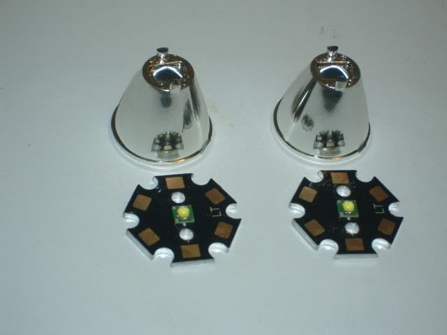 [/IMG]
Alloy angle plate drilled with 4 M2 screws to located the stars and 2 M3 holes to clamp to case and a further M4 hole to fix the Cateye mount. I've added 2 small 3mm holes in the top corners to feed the wire thru
[IMG] 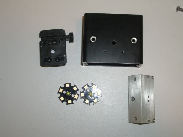 [/IMG]
Picture shows stars attached to angle plate. The 2 additional holes in the Hammond case are for small M2 screws whose heads locate into the underside of Cateye mount and stop it swiveling.
[IMG] 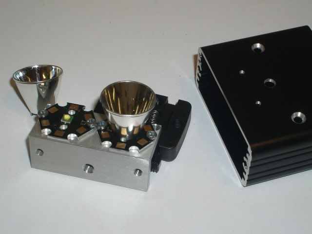 [/IMG]
And this is how far I've got. Probably have to wait a few days until I next get a chance to work on this but not far to go.
[IMG] 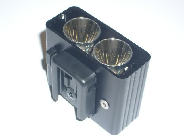 [/IMG]
Nice one CK though you are a veteran on the hammond case`s your input here is great .
I see you have drilled the stars for the reginas Nice touch .
if there was a small bit of ali in there I glue that to the driver just leaving the solder hole so the the whole driver is cooled .
I said if as it is very possible I forgot to include it as the red wine took effect as I was packing them .
and if anyone finds a bit of cheese its mine.
Wish I had got a black one
Trout,
I got the small bit of alloy but was wondering, the drivers isnt on a metal printed circuit board so I cant see the advantage of bonding the underside to a heatsink. Looking at the component side of the board the largest part with 470 on it (correct technical term is of course large black smoke container) looks like a good place to bond to the main case but I've no idea without firing it up what gets hot.
That looks great CK, especially with the black case! I wish I could trust my hand to drill the stars!
Nice work CK.
Any idea on where I can get a M2,M3,M4 tap and die set cheaply for this job?
Ooh, my bits are here as well! Just haven't got the time to have a fiddle until possibly Monday now, before I have to go to court 🙁
I like the way you drilled the start CK, may try that as well.
Whats the shortest anyone would suggest cutting the case down to? Does the minimum size for space allow enough heat dissipation?
Any idea on where I can get a M2,M3,M4 tap and die set cheaply for this job?
Try Tracy Tools, you dont need the dies and if your just working will alloy then carbon steel will do
Whats the shortest anyone would suggest cutting the case down to? Does the minimum size for space allow enough heat dissipation?
My case is 45mm long. I've run this case with Seoul Leds at 1 amp with no problems. I'm assuming the the increased efficiency of the XPG means less heat is generated as more energy is turned into lumens, who knows. Compared to the Buckpuck I've used in the past the driver package is very small, could easily cut the case down another 5mm, if its head mounted its not so much the size but the weight.
Regarding the issue of heatsinking the driver board ..... I hope BCT/Teapot doesn't mind me quoting an email he sent me ... and he may like to add more info .......
"The main two components which generate heat are the main chip and the
inductor (the largest components on the board). Rather than heatsinking
them it would be easier to stick a heatsink on the underside of the
board as the heat spreads around the board fairly evenly. I would
suggest seeing how it goes first and measuring the temperature if
possible. The IC manufacturer recommends keeping the surface of the
package below 65C and the inductor value falls with temperature so the
circuit will not be able to regulate the load as effectively."
I plan to use Troutie's method and bond a piece of ali to the underside (leaving the solder holes clear) and then bonding the ali to the large metal hammond end plate. The plastic bezel will be used to isolate the hammond end plate from any heat that comes from the leds via the case. No point using the Leds to heat up the driver even further!
The main concern heat-wise is the IC - this is the thing with 5 small connections to it. However, heatsinking just it will be fairly impossible. For those who don't know, a PCB is (in this case) a fibreglass core with a thin (about 35um) copper layer which transfers the current around the circuit. Copper is also very good at transferring heat so the heat will spread around the board fairly well. The fibreglass doesn't transfer heat that well but even still enough gets to the underside of the board to make connecting a heatsink there make a difference.
One warning, there are two exposed areas on the underneath of the circuit board aside from the 5 connection terminals. These are at the same potential as the PWR- connection so take care not to electrically connect them to anything else!
Thanks BCT ... I take it a thin layer of AAA will be OK ...it looks like the two exposed areas you mention are very slightly below the level of the mask on the underside of the board so AAA'ing the ali plate to the underside will cause no problem. Is that right?
I forgot to say that I intend to use a "solid" hammond plastic bezel, not the skeletal one for the rear of my builds (that's what I have available), so I will cut a rectangular hole in the bezel, just a bit bigger than the size of the ali plate I intend to AAA to the driver. Of course it works even better if you have the skeletal bezels on the rear.
Woo Hoo my boxes have arrived 😀
I've got the ones with the ali plates and seperate plastic bezels. What would be best to cut or drill through this for the switch etc or swap with someone who only has the full plastic ones?