- This topic has 690 replies, 36 voices, and was last updated 3 years ago by zilog6128.
-
Cheap 3d printer kits – Experiences?
-
stumpy01Full MemberPosted 5 years ago
siwhite Subscriber
Quick Q for the 3DP Boffins of the forum, if I may? Not world ending, but I’d like to find a fix.
My printer (or more likely Cura) settings have been a bit off since day 1. Prints are not centred on the print bed on the Y Axis – I have to drag the model towards the very front of the bed in Cura in order to get the resulting print somewhere close to the middle of the bed. I’d guess it was somewhere in the region of 60mm off.
I have checked the bed dimensions in Cura (correct) and the nozzle touches ‘home’ perfectly in the bottom left corner of the bed.
Any ideas? Printer is a Tevo Tarantula in case that makes any difference, and works very well in every other regard
I can’t be sure, but I reckon you have ‘origin at center’ ticked….
In Cura, go to Preferences>Configure Cura>Printers & then hit the ‘machine settings’ box to the right of the white pane.
If ‘Origin at Center’ is ticked, untick it.If that’s not ticked, then I dunno….. 🙂
NorthwindFull MemberPosted 5 years agoThose relief maps are genius- also the only 3d printed thing ever where layer ridges just look totally fine, because they just end up looking like contours. Nice!
Discovered in today’s big print that if I run my machine up to maximum height, it collides with the roof-hanging filament thing I made and jams, ah well, 24 hour print down the drain in the 23rd hour.
zilog6128Full MemberPosted 5 years agoDiscovered in today’s big print that if I run my machine up to maximum height, it collides with the roof-hanging filament thing I made and jams, ah well, 24 hour print down the drain in the 23rd hour.
You are not the first to make that mistake! Pretty common occurrence on the FB groups, not something you’d really think about until it happens. Good argument to mount the spool off the printer with a reverse-bowden setup (the other being that it looks much cooler 😎)
AlexSimonFull MemberPosted 5 years agoThat’s a shame those relief map links have broken.
Looking at that link you sent, on this page:
https://environment.data.gov.uk/dataset/e9edb9f6-d563-4a5e-a425-c72c5eac919c
Click on the download button next to where it says Survey Download.
Then there’s a new interface which looks a bit more sophisticated than before:
https://environment.data.gov.uk/DefraDataDownload/?Mode=surveyI’ve done another one since for someone who commissioned me off here (actually it was my son that was commissioned in the end as I was too expensive lol).
It hasn’t been given as a gift yet, so I’m waiting to publish the photos.
If you get stuck, let me know by PM.
AlexSimonFull MemberPosted 5 years agoJust looked for Snowdon and I can’t see any LIDAR data either.
Also looked for Betwys and nothing. It does say only 70% of the British Isles is covered. A bit weird that they don’t have data for areas frequently flown past by jets though!EwanFree MemberPosted 5 years agoYeah – guessing they only do bits of interest to flood defences. The mapping seems to be strips, so the summit of snowdon is probbaly of marginal interest to flood defences (tho i’m surprised they don’t want to know about the entire watershed).
stumpy01Full MemberPosted 5 years agoAlexSimon – cheers for the update.
Did you pay for that Accutrans program?
It looks like something I need to have a proper play around with at home in the evening, rather than at work ;o)
AlexSimonFull MemberPosted 5 years agoNo, the bits you need are free. There’s only about 3 operations you need to do.
This gives you sea level as the bottom of your tile:- Open the asc file.
- As it’s opening copy the ‘min’ height number, then ok.
- Choose Dem > Convert to 3D (less water), then ok.
- Choose Tools_1 > Extrude Pseudo 2D surface then paste your number into the ‘Thickness’ box and then check ‘Flat Bottom’ and hit ‘Extrude’ before you hit ‘ok’ (but remember to do both).
- Save as .stl.
NorthwindFull MemberPosted 5 years agoQuick question for the PETG fans- if you’re in an enclosure, what’s a good air temp? Finding it randomly hard to find any info online. I’ve produced some nice functional parts but they’re not as pretty as I’d like so I’m just working through all the settings.
zilog6128
You are not the first to make that mistake! Pretty common occurrence on the FB groups, not something you’d really think about until it happens
It’s worked out well in the end, finally relocated the filament spool so that it generally is a bit less in the way, and also did some minor setup changes, added a new filament guide and eked out a bit more print area size (officially it’s 150x150x200 but I’ve got it up to 165x155x220 now basically by doing away with the safety margins, just losing a wee bit for the glass bed clips now)
PS, thing what I am printing- a bit of wargame terrain for a friend of mine. Chose this queasy pink carefully, it’s worked out great
 stumpy01Full MemberPosted 5 years ago
We’ve struggled getting PETG to print well at work on our Ultimaker and that’s using Ultimaker filament and settings.
But I think AlexSimon had good results with the bits for his CNC router, so he might be able to offer some suggestions.
That terrain thing looks interesting! Seems to have printed well.
What fang are you using on that printer?
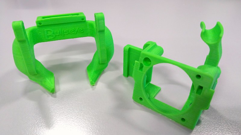
I’m currently printing a Bullseye fang from the bloke who designed the Petsfang.
It’ll be my first proper mod to the printer, really. Everyone seems to be running some kind of fang, so I thought I’d get in on the act, although I didn’t wanna go to the trouble of soldering on a new fan. Apparently this Bullseye fang makes best use of the relatively small amount of puff from the stock cooling fan.AlexSimonFull MemberPosted 5 years agoLooks good Northwind!
My PETG settings were fairly stringy, and it was prone to warping without Elmer’s, but not bad otherwise. I don’t have an enclosure, but I was trying to print in zero temps, so I put a plastic sheet up in front of the printer (it’s on a shelf so a little enclosed).
But I’ve only ever tried the one PETG filament (Real Filament of Amazon), so I don’t know how universal the settings are.The CNC is amazing though. Loving it. Cut some acrylic today for the first time and it went really well! For the moment I find it much more exciting than 3D printing as it does stuff with wood, but whereas I completely ignore my 3D printer once I set it going, the CNC needs constant monitoring – easy to start fires apparently
NorthwindFull MemberPosted 5 years agoThe fang is a random thingiverse- but pretty well developed, I think it’s about a 3rd remix and it works on all the recent creality printers. So nice to have a user scene again after the total desert of the Anet A4. It’s actually my most succesful PETG print so far, it was stringy as hell and a wee bit boogery but it cleaned up easily. I don’t know why but I always print my printer parts in orange.
(the ender has awful stock fans so it was no hardship to upgrade to a couple of decent 40mms- much quieter as well as better flow)
TBH I’m really pretty pleased with the print quality- that’s PLA in that pic but my ABS is pretty much the same. The PETG I’m nowhere near, it prints strong and straight but absolutely plastered in defects in any large part. Usable but fugly
But I usually print at .12mm so it does make the prints pretty slow, that’s 22 hours in (with thick walls and base but only 20% fill). Those organic looking terrain parts are really picky, there’s no straight edges which does help but layer lines just look terrible on it- but the model is ace, I’ve scaled it from about 50mm to that 220mm beast.
I just saw how much baked on crap there is on the hotend! I am ashamed.
stumpy01Full MemberPosted 5 years agoWell, the Bullseye fang printed remarkably easily. I printed with supports on the build plate only with a support overhang angle of 70 degrees.
Annoyingly, the designer recommended setting a support density of 40% (although wasn’t any clearer than that) and realistically this was massive overkill – a great deal of the print time was taken building up a pad of support material underneath the main horizontal part of the duct itself.I think I need to give my printer a bit of TLC as the print quality seems to be suffering a bit lately & I am not convinced I’ve got my retraction settings quite right.
The intention for this was to print it well enough to get it installed & if it works well do another one much slower and at higher resolution (probably 0.1) to get a better finish; which the improved cooling should help with.[url=https://flic.kr/p/2ewX7M1]Bullseye Fang for CR10 Mini[/url] by STW stumpy01, on FlickrAlexSimonFull MemberPosted 5 years agoThere’s something really satisfying about designing, building cncing and 3d printing an assembly and then screwing it all together with stainless hardware. It just makes it look ‘proper’.
This is a dust shoe for my CNC – just need to buy a cheap dust pan brush and silicone in all the bristles.
Really pleased with how it’s all come out although all my internal edges need a little working – they always seem to come out undersized.
stumpy01Full MemberPosted 5 years ago^^nice. Yeah, it’s very satisfying when you put a series of parts together into your own assembly.
A colleague of mine has done some tests with pausing a print in the gcode at a certain layer height to insert nuts into hex pockets & then print directly over them to encapsulate them & provide robust fixing points. It worked pretty well.
Regarding the brush strip – could you not get something pre-made, like this:
AlexSimonFull MemberPosted 5 years agoThose ebay links could well work. I didn’t fancy waiting for China post, but one of those in the UK. But then I can get a brush for £2. Hmmmm. I might just go the DIY route. A few youtubers have done it successfully.
My first thought was a draught excluder, but people have said they are too short usually.NorthwindFull MemberPosted 5 years ago@stumpy, this is a trivial one but I reckon you might have a mismatch between stepper… ur, step size, whatever that’s called, and layer thickness, just from those occasional thicker layers you have that look like z banding but not quite.
I had the same- I’d set it to .1 layers but the stepper resolves at .04 so every third layer it was mismatched. Changing to .12 gave no loss of quality because it just meant all the layers were .04, but gave it more consistency. Sneaky! (your sizes may vary due to belt tooth sizes and that)
Alright chaps, what do we know about nozzle size? As above, I pretty much always print at .12 with a .4 model (my ABS rafts are fatter, at .8, but they print 1/3d as fast). I’ve a feeling I should downsize the nozzle, since I’m never running it at capacity anyway and it’s probably losing some detail, basically I’m painting with a big brush. Any thoughts? I know some materials get bad tempered with really small nozzles but I’m thinking maybe just a .3 for a slight change.
AlexSimonFull MemberPosted 5 years agoI’ve never done anything other than 0.2 layers with a 0.4 nozzle.
I considered buying a 0.6 because I was getting clogs with my wood filament, but never got around to it (and was a bit scared of changing a working system).
Would be interested in hearing others thoughts on this too.NorthwindFull MemberPosted 5 years agoI mostly print little parts (on a little printer!) these days so I think that’s why I’ve gone so biased towards thin layers. It’s also a really easy way to add quality without all that tiresome “doing it properly”
stumpy01Full MemberPosted 5 years ago@northwind – yeah, I’m aware of the 0.04 multiples thing. Thanks for mentioning it though.
This was set to 0.2 so should have been OK.
That was a particularly bad print to be honest, very ugly and I’m not sure why. I suspect that this Hobbyking filament isn’t the best quality – and the green colour really shows up any issues.
I think one thing I need to do is get some grease on my Z-screw.Regarding nozzle sizes – on our Ultimaker 3 at work we have 0.25, 0.4 and 0.8.
The 0.25 gives very fine detail, but Jesus it is slow. If you are printing small figures and stuff, then give it a whirl. You could always set up a suitable profile in Cura with a smaller nozzle and see what difference it makes to print time.I really like the 0.8 nozzle to be honest. For most of my practical widgety bits, I reckon a 0.8 or perhaps 0.6 would be a good idea. But it’s obviously a lot coarser than the 0.4 nozzle! You sacrifice detail, but gain speed!
If I was doing a lot more printing or perhaps selling things, I’d probably have a second printer set-up running a larger nozzle.Have you looked on Youtube? There are some good videos comparing nozzle sizes and how the quality changes.
NorthwindFull MemberPosted 5 years agoAh, sorry bud, I misread your post and say the “go down to .1” comment as if it were “this is printed at .1”
I think the thing I’m trying to figure out most is the impact of a smaller nozzle other than print quality- it’s hard to get a solid answer on whether it’ll be genuinely slower, since I’m essentially printing down to that level despite having a normal sized nozzle. I suspect that I might actually be sacrificing quality but not gaining speed (I mostly print at 75m/s but I have my walls set slow, it makes such a difference on this printer)
Well, anyway, I’ve just started a nice model which should be a good testbed- doing it with the .4 now and I’ll swap to .3 and do it again tomorrow
stumpy01Full MemberPosted 5 years agoI guess the speed difference comes very much down to ‘it depends’ based on what you are printing.
If you need a strong part, so want walls that are ~1.5mm thick, you’ll need 4 walls to achieve 1,6mm with a 0.4 nozzle and 6 walls to achieve 1.5mm with a 0.25 nozzle.
And if you have a lot of bottom/top layers, they will take significantly longer with 0.25 nozzle as your area covered per second is smaller. A 0.25 is effectively covering 60% less area per second. (0.25×1.6=0.4)This is where the 0.8 nozzle really comes into its own if you don’t need the detail. A 1.5mm wall can be despatched in 2 walls, the top/bottom layers are covered twice as fast and printing at a 0.4mm layer height is trivial.
NorthwindFull MemberPosted 5 years agoVery true, if I was printing larger or structural parts that’d definitely become a much bigger issue. It’s pretty hard to take general info and adapt it to your own specific case I find.
NorthwindFull MemberPosted 5 years agoOK so, if someone really didn’t want to learn a proper modelling software, but had some very minor changes they wanted to do to an stl (literally just chopping bits in two for 2-part printing), what would be the simplest and least effort way to do it? I used to have some free software that I used for this stuff but I’m damned if I can remember what it was
stumpy01Full MemberPosted 5 years agoI’ve never done it, but I think meshmixer is the one that everyone uses.
If you search for something like “STL split with meshmixer” on YouTube, there are plenty of vids…zilog6128Full MemberPosted 5 years agoIf it’s literally just splitting the model into parts for printing you can probably do this in whatever slicer you use. You can do it in Slic3r (which I use, and is free)
NorthwindFull MemberPosted 5 years agoCheers stumpy.
Possibly I used to just do it in slic3r, I’m using Cura now- not even sure why I changed! And it doesn’t have an easy way to do what I want here.
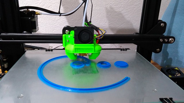
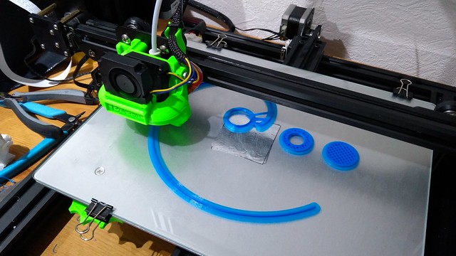
stumpy01Full MemberPosted 5 years agoI got round to installing the Bullseye Fang on Saturday night after half a bottle of red wine!
It was very easy to do. My main concern was yanking some of the wires & breaking something, but I actually had no problems.
The results are, erm……hmmm, I think I need to do some tweaking of the placement.Good news:
– nozzle visibility is massively improved.
– print quality is marginally improved. And I mean cigarette paper thin marginal improvement.I printed 3 items before changing & re-printed them after with the same gcode.
A bridging test, which looked surprisingly good before making the change. I expected a mass of drooping filament, but it was mainly OK. After changing, it is a bit better, but barely.
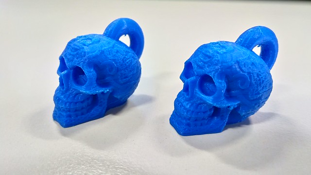
The Celtic skull keyring thing – there are a few droopy bits of filament around the back of the jaw, which I thought might be improved. But they are virtually identical. Without having labelled them, I would not be able to tell the before & after apart.
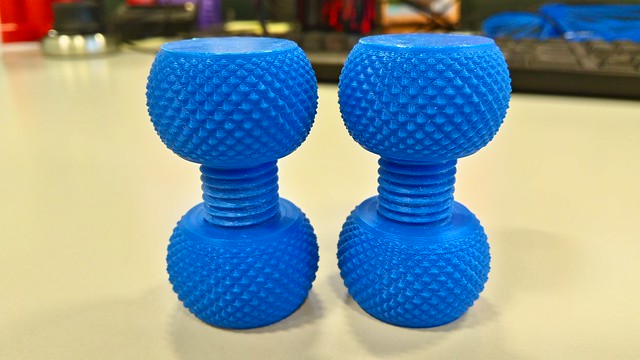
The knurled nut & bolt – here there is a difference. The pre-fang one is strange in that the nut will screw onto the thread one way, but if you flip the nut then it won’t screw all the way down.
The post-fang print works both ways, so i suspect it is a bit more dimensionally accurate, but the overall action of the thread is not as smooth.Looking at the comments on Thingiverse, it could be that I have mounted the fang a bit too low & need to raise it up a bit. I might scooch it up a mm or so and see what happens.
Anyway – obligatory pic overload:
Fitted & printing
[url=https://flic.kr/p/2dqbhB8]IMG_20190217_000245[/url] by STW stumpy01, on FlickrCeltic Skulls – there’s a band at the same height that I need to investigate.
For reference, that part is only about 25mm high.
[url=https://flic.kr/p/2dqbLSB]IMG_20190218_090543[/url] by STW stumpy01, on FlickrKnurled Nut – I think it’s an M10.
[url=https://flic.kr/p/2dqbLUF]IMG_20190218_090729[/url] by STW stumpy01, on FlickrBridging Test – can’t really see any difference from this distance at all. Even close up, it’s subtle.
[url=https://flic.kr/p/2dqbLUv]IMG_20190218_090847[/url] by STW stumpy01, on Flickrzilog6128Full MemberPosted 5 years agoNice. Did a similar thing with my printer. Worth it for the extra visibility on the nozzle alone!
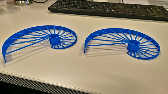
celticdragonFull MemberPosted 5 years agoHad the day off, and after having an idea, and discussing it on the Trans con facebook page, when someone else had a similar idea and posted it, I’ve been making the prototype of a bike accessory!
I originally bought the printer to make bike parts for myself, but so far have only manged to make 1, the rest being anything but bike parts!!
Please excuse the naff photos. Its a tri bar brace, or will be when the carbon bar turns up, to hold a go pro and front light.
Funny isn’t it, that as soon as you print a design, you can see design alterations taht could work!
zilog6128Full MemberPosted 5 years agoThat is the beauty of owning a 3d printer though! just tweak the design & run off the next version!
stumpy01Full MemberPosted 5 years agoFunny isn’t it, that as soon as you print a design, you can see design alterations taht could work!
That’s part of the benefit of it, I reckon!
Many times at work we design stuff, get it sent off for manufacture & it takes ages & costs a bomb, then as soon as we have it in our hands we realise it would have been so much better if it had been Y instead of X……There’s not a great deal we can do in 3-D printing with regard to functional prototypes where I work as the parts are either too big, need to withstand v high temperatures or are too high precision for what a current FDM printer can achieve – often it’s all 3 of those.
But, every now & again we get something that is the perfect candidate for printing. The best thing is when we have a request from someone who has no real expectation, but just wants something they can print out to get an idea of how big it is, how easy to hold/manipulate or whatever.
They are always surprised at how good the part is & it normally spawns a whole heap of suggestions for modifications/improvements etc.papamountainFree MemberPosted 5 years agoNice Stumpy. Where’s the second fan? Do you have the link for it? Is it from this? https://www.thingiverse.com/thing:2759439
Which of the files did you need? Thanks.
I put stepper dampers on the other day. Still prints fine, quieter now obvs. Really need to sort the control box fans now, they are the next loudest bit!stumpy01Full MemberPosted 5 years agopapamountain Member
Nice Stumpy. Where’s the second fan? Do you have the link for it? Is it from this?
Yeah, It’s from the Thingiverse item you link to. Basically, he has optimised the duct design for the smaller output stock fan, rather than one of those large 5015 blower fans, that to be honest I can’t be bothered soldering in place.
As for files, I think I used:
Bullseye__Base_Creality_9.27
Bullseye Duct_9.273rd & 4th ones down in the file list.
If you download the ‘creality_files_to_print_11.3’ pdf file then it should be pretty clear from that.
He’s got a website with some nice details & videos etc.
http://www.dpetsel.com/because-you-asked.html
You need a few new screws & nuts – M3 nuts & I think M3x12 screws. These are detailed in one of the pics on the Thingiverse page.
The second fan is sitting behind the part cooling fan. Here’s a pic that should show it a bit clearer:
[url=https://flic.kr/p/2dqbhBi]IMG_20190217_000124[/url] by STW stumpy01, on FlickrI keep meaning to get some stepper dampers. Did you mount also print out the Y-Axis brace to support the Y-Axis stepper? Without it, I think the damper fails quite quickly, as it shears.
Something like this: https://www.thingiverse.com/thing:2701747 although you need another damper on the back-side I think.Another thing I keep meaning to get round to, is sorting the control box fans. There is a stand available that takes 120mm cooling fans – so you remove the base of the control box & sit it on some larger fans. I’ll probably print that & wire some fans up.
https://www.thingiverse.com/thing:2729888oliverracingFull MemberPosted 5 years agoWhat strategies does everyone use in terms of fire prevention/suppression? I’ve seen a fair few reports of fires online (mainly on the Anet A8) and last week a mate had a scary one where his got to the smoking point after a mosfet stuck on. I had a heater cartridge fall out of my Tarantula a while back but didn’t think much of it as it failed pretty quickly and did no damage.
From this I found the thermal runaway and all the safety checks had been disabled in my firmware.
This has now been rectified, and I’ve got a smoke controlled relay in the post to cut power in the case of a small fire and have a flame activated fire suppression ball (explodes powder when exposed to flames) sat just above the printer in the worse case scenario. What I am wondering is if my Correx enclosure and sitting in on a plywood shelf is a good idea!
Since reading about the fires I have stopped using my printer when I’m not in the room and I want to get back to the point where I’m happy to at least go into other rooms for more than 30 secs!
stumpy01Full MemberPosted 5 years agooliverracing Subscriber
What strategies does everyone use in terms of fire prevention/suppression?
Currently – nothing. Hmmm. Not great, I know.
I need to update the firmware to enable the thermal runaway stuff, but for the CR10-Mini this required an Arduino & plenty of fannying about, which I predictably haven’t got round to.
I have a degree of confidence (perhaps misplaced) in my printer, as I have put plenty of hours through it & am generally quite diligent when it comes to checking for frayed wires/wear etc.
I have considered one of those fire extinguisher balls – ideally I’d stick the printer & ball in an enclosure, so if it does go off, I don’t completely trash the room it is in.
Definitely something to think about.
zilog6128Full MemberPosted 5 years agoFrom this I found the thermal runaway and all the safety checks had been disabled in my firmware
I did google a while back, only found one substantiated report of a proper fire and this was the exact cause. So just don’t do this and you should be ok 😀
I think the risk is massively over exaggerated, no more likely than any other electrical item spontaneously bursting into flames, so take no special precautions with my 3D printer. I do monitor it via webcam when I’m away from it although that’s more so I can stop it if there’s a problem with the print.
oliverracingFull MemberPosted 5 years agoMosfets failing on is another known cause of fires, in the case of my friends it was only his quick thinking that saved it (walked into garage full of acrid smoke so killed the power). The bed had got hot enough for the pla print to be a pool of plastic dripping on the hot power wire (the cause for the smoke) and it had completely warped the plastic frame and left black scarring on the wooden bench where the wires were. I guess the wires were under rated to have been able to get so hot even with a stuck on mosfet.
Will see if he took any photos as I know he dismantled and binned it all to hide the near fire from his wife!
papamountainFree MemberPosted 5 years agoThanks for the fang details Stumpy. Let us know how you get on with it.
No, I didn’t print a y-axis brace for that stepper. I can see what you are talking about and it’s seems plausible. Will see how it goes, they only cost a cpl of quid so if it breaks ill get another or two and go with the brace.
That control box fan thing was what I was looking at too. Would be nice if it actually screwed to the box, I think the box just sits on top. There’s a remix which addresses this but it’s a one part print which is too big to print on our beds I think. I’ll probably just go with the first one.


The topic ‘Cheap 3d printer kits – Experiences?’ is closed to new replies.