Sorry Smudge 😳 ..... Dynamos are not for everyone, so I think you are safe supplying MTB batteries for some time to come! 😆
I'm lucky in that I have a bike with a dynohub and another without. After building the battery lights, I realised just how easy it was to adapt the design to a dynamo. Not trying to do BCT out of business either! Swap constant current driver board for 8 discreet components and away you go!
I've got over 80 night miles now on the twin lights - battery version, on road and track and the versatility of a dip and main beam, both with switchable levels is sheer luxury. I’m keeping the dip on low (25%ish) or medium(50%ish) when I’m on the road and have not had any negative reactions .... yet! The dynamo version on the hack bike is set like the dip beam on medium on the Kraken .... nominal 500mA, and will be used mainly on the road. On the tracks with the twin lights, the dip on full power is excellent and picks up all the crap you want to avoid well in advance of running over it. The spill is great to show detail at the sides .... but as someone else pointed out, would be great to direct the upward spill to a more useful place .... downward. OK can’t have everything!
Main beam is just like the dip beam ... only it shows stuff up well in advance in the distance, cos’ that’s where it’s pointing! Great throw.
Hope the dynamo stuff hasn’t clouded the build for those only interested in battery builds. Troutie’s latest post sums it up simply to get it back on track.
BCT – yep! It’s a very simple dynamo circuit .... and fairly cheap too. The low speed flicker is really not a problem unless your riding style means you stay below 5mph a lot! Even my old legs manage a tad more than that!
As for optimisation of the dynamo output issues, they seem to be from an age when we tried to eek out every last lumen from incandescents or early low output LED .... there really is loads of output using that simple circuit and just 2 * xp-gs/reginas. You can go mad and add more xp-gs/reginas with the same basic circuit and, assuming you are happy with the extra leg power needed, produce “Baby Trout” type levels.
I know it goes against the grain slightly, but with cheap blinkies running for 50 - 100 or more hours on a couple of triple A’s or AA’s, I went along with the suggestions of several veterans of the dynamo led brigade and decided that the complications of a standlight (especially for my first dynamo build) outweigh the benefits. You don’t need a standlight off-road (do you?) and on the road, a second of darkness or flicker before you get loads of light when taking off from traffic lights/Junctions is taken care of by the blinkie. Check it yourself to see how short a time it takes to pass the 5mph mark from a standing start!
Hi Lipseal ..... if you're down this way again anytime, I'll show you the dynamo build output.
BCT gift sent for driver kit.
Done the same as Flicker here and blown one of my LEDs!
Troutie can I buy one of the LED on 20mm stars off you. I was playing with the reginas and must have shorted one of them out- have checked the other one is still working.
my bits from BCT arrived today and its time for some more questions.
Firstly how weatherproof is the power connection going to be? Will it need some extra stuff doing to it?:
[IMG]  [/IMG]
Secondly, which of these 3 pins is which? I was expecting only two:
[IMG]  [/IMG]
Connector not likely to be massively weather-proof to be honest. If you want something that will take all-seasons riding then you really need a properly waterproofed connector.
The bigger pin, the one to the right on your photo, connects to the striped wire on the power lead. The one to the left connects to the plain lead. The one on the top is not used here - it connects to the left-hand one when there isn't a plug in the socket as a sort of bypass switch for mains / battery operation.
Not sure what others think but my feeling is that really a basic multimeter is a pretty much essential piece of kit for a build like this just to check things out and test the correct voltages are in the correct place and no shorts are present.
cheers BCT, will look into a multimeter. Any recommendations on where i can get a decent weatherproof connector from? I had intially thought about having a short ~10cm stretch of cable coming out of the box and then having the connection from the battery there if that makes any sense?
Actually scratch that idea, i'm guessing just squirting some silicone round the gap will do the trick. If water did manage to find a way in what damage would it do and to what?
Not sure I follow - are you meaning the gap between the plug and socket? If so, surely that means you'll have to re-silicone each time you unplug it?
Water and electronics are generally not a good idea, at best it could cause the circuit to malfunction as water is a conductor (albeit a poor one). There are also corrosion issues - although PCBs are cleaned with water after soldering they are then dried thoroughly.
yes between the plug and socket, i doubt i'd be unplugging it all that often so I think this would work.
Another option, would be to have a cable going directly into the light then some sort of connection from the battery to said cable. A bit like CK's build on page 13, the only problem is I have no idea what i'm searching for on the internet. He calls it a cable entry, but this is fruitless on google etc. Any ideas?
so im thinking chop [url= http://www.dealextreme.com/details.dx/sku.32751 ]THIS[/url] cable in two bits, one end connects directly to the battery, the other to the light. Have the socket and plug connect about 20cm away from the light. Faesible? If so i'd just need a cable entry for the light housing as mentioned previously.
Dont forget a small cable gromet and some ods and sods bits of surplus cable comes from me posted yesterday
Jammy - that looks a good cable, someone should probably do a group buy of them. You either need a grommet or better would be a cable gland but they are fairly chunky. The other option is to use the plug / cable on the light and mount the socket somewhere with the battery out of the weather.
cool ill give that a go then using the grommet that troutie supplies and the cable from DX. does anyone else want one ordering? Ill order on tuesday so if people add their names to a list ill get that sorted then shipped out to people (should be about £2 in total).
Next question is about how to wire battery holders together 🙂 Ive hacked one of BCT's 18650 4 cell holders in half to create 2x2 cell holders that will fit together inside a water bottle; but i've not a clue about which terminal needs wiring to which. I've found this diagram on the net, but dont know which I want: http://www.electricfence-online.co.uk/shop/renewable-energy/renewable-energy-advice-faqs/battery-bank-wiring.html
If you are stuck for weather/water proof connector, then have a look here:
http://www.vehicle-wiring-products.eu/VWP-onlinestore/connectors/multiconnectors.php
Lots of other useful bits and pieces listed as well.
Hth
Marko
You're best wiring them as a 4S pack, in other words all 4 in series so +ve from one battery goes to -ve on the next and so on until you are left with a + from one battery and a - from another.
Hope you realised how slow DX are.... Unless you are fortunate you'll be lucky to see anything from them within a month.
brilliant cheers, i managed to steal a mates cable he has for his magicshine on the proviso that I get him a replacement, so its him that will be lumped with the wait 🙂
A further question (i promise the guide i write will be worth it) is it necessary to bond the new driver (BCL01D)/ali combo to an ali end plate? Will it be ok if it is glued to a plastic end cap?
If it does need an eli end plate anyone want to swap one for a plastic one?
The new driver runs 5-10 degrees cooler. Not sure what temperatures inside the box are like, you may get away without the extra cooling. Another option, if you have enough case length you could bond it to the top or bottom of the main case.
Thanks to Troutie and BCT for their help with these bits. Here's my attempt - a bit "Jonny 5" but they then match the bar lights!
[IMG] 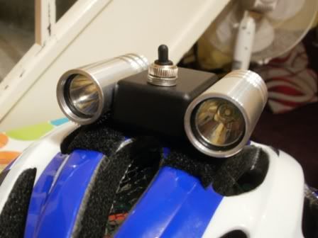 [/IMG]
[IMG] 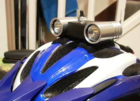 [/IMG]
[IMG] 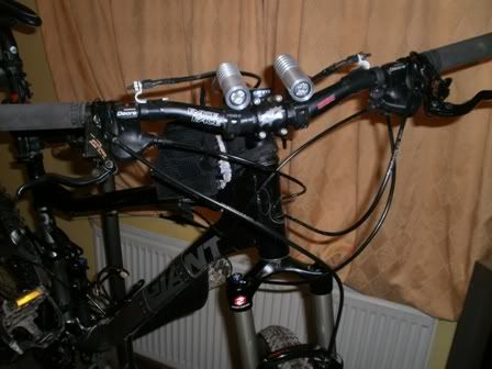 [/IMG]
BCT and Troutie, you should have Paypal's shortly for two more sets if that is ok.
Cheers,
Keef2.
Another option, would be to have a cable going directly into the light then some sort of connection from the battery to said cable. A bit like CK's build on page 13, the only problem is I have no idea what i'm searching for on the internet. He calls it a cable entry, but this is fruitless on google etc. Any ideas?
My cable entry is a 4mm bannana plug socket with the internals drilled out to take this cable http://www.maplin.co.uk/Module.aspx?ModuleNo=23087&OrderCode=XS91Y. The cable is bonded in with epoxy, this is my main mechanical restraint the boot over the top is a strain relief from a BNC cable but a bit of shrink sleeve will do. I use these connectors http://cgi.ebay.co.uk/2-way-Weatherproof-Superseal-wiring-connector-/380292047586?pt=UK_CarsParts_Vehicles_CarParts_SM
Jammy111 have a look at the pictures I posted a couple of pages back, the magicshine extension cable is what I have used. It's water tight and works perfectly with the cable grommet that Troutie supplies. You can pick them up off eBay for £5-£6, so you don't need to wait weeks for DX to ship it to you.
looks good flicker! where have you attached the driver in your build? Do you reckon it will be ok to attach the driver/ali combo to the plastic end plate with some silicone adhesive?
Also how have you weatherproofed the case? Silicone around the screws on the bottom i presume but what about the end caps in particular, that is pretty much the last thing i need to know then i should be good to get the soldering iron out!
Woah keef2, what are those light bodies made from?
Jammy111, I ran a bead of silicone sealer around the inside of the plastic end plates and a little blob in the screw holes.
I used AAA to stick the PCB heatsink to the top of the case, after I'd finished wiring it up and testing it.
The leds are housed in 24mm Aluminium Bar, bored out to 21mmx23mm on a little hobby lathe (C2). They're about 50mm long. Looking at Chelboed from MTBR has done I could probably afford to go smaller and lighter. The driver sits in the litle black box which was a maplins miniture hamond special. Just been out for an hour with them round a bit of the Quantocks and they work great.
Hi Keef2 ... got a linky for that Maplin box? Looks useful.
Also, where did you source the lens cover and o ring ... did you groove the tube for the o ring or just silcone it?
next question 🙂 When sorting out my 18650 battery pack is there going to be any reason to connect 4 rather than just 3 cells. The run time should be the same, just the voltage should be higher, correct? 3 batteries will churn out 11.1V which should be enough, is there any reason to have 14.8V instead?
Cheers,
J
EDIT: apologies if this is a really stupid question, it has the potential to be...
i`m liking the pipe bomb lights. how do you fix the led in place?
this leads me to think about if there is a way of using hte led without hte bulky driver - ie mini head torches?
this leads me to think about if there is a way of using hte led without hte bulky driver - ie mini head torches?
This is exactly what I want to do - a joystick style single xpg unit with a single 18650 in it, but I've not looked to see if anyone else has done it yet. Its obviously possible as thats what the new Joystick is, just not sure about the driver options. I'd also like to upgrade my old P4 Joystick to an XPG though I'm not sure if the driver or optics would be any good. I can't even find any sites where someone has dismantled their joystick, maybe I'll be the first!
Answer is yes should be a straight swop if the new stuff fits in the joystick
should use the driver in there too .
failing that then a 1 ohm resister will let you use it at 1 level 1000ma drive
or a 1.2 ohm for 700 ma drive .
Jammy you can use 3 cells no problemo
in my tesco cree torch there is a circular circuitboard attacehd to the led i presume is the driver.
I think Trout, earlier in this thread, was messing with using just resistors? lord only knows what page that was mind... or how you would go about doing this.
(edit) beaten to it by the man himself - thats service!
that said if the stars are circa 25mm you should be able to get a driver in you are just makinghte light longer to accomodate all the gubbins.
A single 18650 will give crap run times though?
trout,
when you say:
failing that then a 1 ohm resister will let you use it at 1 level 1000ma drive
do you mean if a 1ohm resistor was wired on the power supply the led would run ok?
i`m guessing the higher the 'drive' the brighter the led?
The LEDs are Thermal Adhesived in place, the the reflector is silicon squadged on to the star. The plastic cover is cut from a EN166B full face cutting visor, held into place by a 3/32" o-ring that is half seated in to a groove lightly greased with more squadge.
Nothing seems to rattle, and they survived it when SWMBO knocked them off the top of the wheelie bin on to the tarmac last night, although I did have to buff out some scratches.
The bit in the middle is one of these:
[url= http://www.maplin.co.uk/Module.aspx?ModuleNo=43710 ]Miniature General Purpose ABS Box 1551 Series[/url].
The driver is on an ali block AAA'd to the case. Nothing seems get warm... yet.
Van Halen
Yes if you have 1 18650 cell and wire the 1 ohm resistor in series with the led you will get 1000 ma drive current from the 4 volts the cell will be at fresh off the charger now as the voltage drops so will the drive current so the led will slowly dim as the battery depletes
You would need a 1 or 2 watt resistor as it needs to disipate some heat .
a 1.2 ohm resistor will give you 700 ma drive and as the resistors go up in value so your drive current goes down .
this is a nice little programme
http://led.linear1.org/led.wiz
I have a dual Hammond running like this for a while now .
its how Ayups are working .
so there is no difference in run times/brightness etc between using 3 or 4 18650s??
Of course there will be a difference in run time 4 cells will go further than 3 cells .
but with a constant current driver like what BCTs is the brightness will be the same whether 11 volts or 14 volts
cool, thanks (told you it had the potential to be a stupid question)
Hi Jammy ..... same brightness for 3 or 4 times 3.7V cells because of BCT's constant current driver ... it works with any volts between approx 8 and 24 volts.
However, due to electronictrickery, the higher the voltage with the same capacity cells (mAH milliamphour) give longer run-time.
If you have 3 x 3.7V 2400mAH cells and run the light at full power you should get about 3 & 3/4 hours.
With 4 x 3.7V 2400mAH cells and run the light at full power you should get around 5 hours.
so with 4x3.7 3000mAh batteries it will last a lifetime on full power, sweet 😀
Well ..... I'd want (and have had!) more than 6 and a bit hours for my lifetime! 😮
Do they really make 3000mAH 18650 li-ions? Or is it one of those 900 lumens out of a P7 marketing hype jobbies? I thought you bought [url= http://bestofferbuy.com/UltraFire-Protected-18650-3.7V-2400mAh-Lithium-Batteries-(2-Pack-Grey)-p-16054.html?currency=GBP&utm_source=gbase&utm_medium=cse&utm_campaign=gbase ]these?[/url]
If they did make genuine 3000 mah cells then I am sure Smudge would be stocking them and certainly I would be wanting them for the Libs
I will give him a poke and see what his reply is .
ultrafire 3000mAh protected cells on [url= http://cgi.ebay.co.uk/ws/eBayISAPI.dll?ViewItem&item=110576073884&ssPageName=STRK:MEWNX:IT#ht_1315wt_907 ]ebay[/url]. I've no idea about the brand, but i'd presume they aren't really 3000mAh as i think they are cheap foreign stuff. Still I got 4 for 12 quid posted so cant complain 🙂
Personally I only use high quality 2.6Ah Samsung Li-Ion cells, not cheap but you pay for what you get.
As for the 3Ah cells, chances are unless youre buying top quality cells they wont be 3Ah and if they are they will be pretty expensive, besides the cycle life will be pretty reduced as something has to give having that extra Ah inside for the same size can.
In essence, there are two types of driver / power supply. The old-fashioned linear supplies burn any excess voltage as heat. Switch-mode supplies like my driver are able to convert a higher voltage at low current to a low voltage at high current with minimal losses but at the expense of a more complex circuit.
With a linear driver the current out is the same as the current in. With a switch mode driver the power out is pretty much the same as the power in, taking some small losses in to account. To explain, two XPGs at 1A would represent about 6.6W of power (3.3V x 1A x 2) Using a 11.1V battery and a linear driver this would mean 11.1-6.6 = 4.5W of power would be dissipated as heat in the driver and in effect wasted. A switch-mode driver assuming 90% efficiency would use about 7.3W of power so at 11.1V this is about 660mA.
Increasing the battery voltage to 14.8V and the linear driver still draws 1A but now you are wasting 8.2W as heat. The switch-mode driver still draws 7.3W which is just under 500mA. (Current = Power / Voltage)
When you are talking single LEDs from single lithium cells then the issue of drivers gets a bit more complicated. The battery voltage is only just above the LED Vf so the wasted power in a linear driver is small, often making them as or even more efficient than a switch-mode driver, plus they are usually cheaper as they are simpler.
managed to get my new driver fitted last night (cheers blackcattech :D)
and took the triple for a spin.. only down an unlit country road but pretty impressed with the output..!! seems slightly more light than my old 20Watt philips Masterline halogen light.. but with a much colder bluer colour..
slightly 'spotty' beam though and am thinking of using a different optic on the middle LED to give a bit more flood close to the bike.. (and keeping a regina either side to keep the spot)
what optic would anyone reccomend for this purpose?
its addictive this light building business! 😉
http://uk.farnell.com/ledil/ca10931-boom-w/ssc-p7-acriche-ref-tape-base-wide/dp/1817773?in_merch=New Products&MER=i-9b10-00001144
farnells do these - i guess might work to give more flood?
for a quid a pop its got to be worth a go?