Apologies to Troutie for a slight thread-hijack here but I'm after some advice from the DIY brigade.
I'm looking at the possibilities of designing a driver with microcontroller built in but I'm not sure just what is needed and what is a pointless extra. The basic spec will be 1.5A output, control from a push-button, thermal limiting and battery monitoring. I'm also intending to have reverse input protection and a PC interface as an 'extra' to make setting up easier.
Are there any suggestions for other things to add?
What input voltage range is desirable? Would, for example, 20V be sufficient or is 24V a must-have? (20V would simplify quite a few things and allow performance improvements)
What is the preferred shape / size? I've been considering a 1" circle similar to the bflex but this is making things awkward. Rectangular boards are much easier to lay out so would there be any major problems with going that way and if so what maximum sizes could people live with?
I'm looking at two versions, one a boost reg, one buck. It may be possible to scale the buck reg up to higher currents at a later stage, the boost is probably limited to 1.5A for most applications.
Reduced current modes will of course be present but I'm wondering if anyone knows if the bflex-type drivers actually reduce the current or just pulse full-current at a limited duty cycle. My idea was to have a 1.5A limit and for say 350mA to limit the duty cycle to 23%. The problem is if you are using it with a 1.5A capable LED this is no problem but lower current LEDs often can't take such high currents even as short pulses so although the mean current is OK the peaks are too high. Actually reducing the current is a PITA though but if necessary can be done.
Bear in mind that I'm only considering hardware capabilities here - this is going to be a collaboration with the software being designed by someone else. (I'll let that person add their own stuff if they want to, won't mention names at this point as I've not asked if it is OK to)
No Worries at all if it means we get some good stuff to play with .
20 volts is a bit limiting as it falls just outside a 5 cell Li Ion
so 24 would be better .as quite a few folks use 18 volt drill batteries which come of the charger at 21 volts .
With the XM-L`s coming along then 2 amps or even 3 amps would be desirable .
All the Taskled drivers Bflex Maxflex ect are true constant current drivers and lower the drive current for dimming
no pwm in them . there seems to be an aversion to pwm drivers in the diy mob
Single sided is easier to mount in a case .
re the modes then there may be trouble ahead .
one mans ideal mode ie hi med low is not ideal for the next man .
but if you have the memory to put in a few differing modes then great .
size as small as poss but probably rectangle not square
Trout are you able to confirm you received payment OK for my order?
Just want to be sure as have had a few problems with local post recently.
BCT your bits arrived yesterday, many thanks. If you get a moment could you check the wiring diagram I posted a few posts back and make sure I understand the new driver wiring.
Thanks
Paul
hi Paul
posted yesterday first class so you should have had it today
but I guess the PO is pretty busy
Troutie
MK - diagram looks fine, just check the polarity of your power socket. You are showing it as barrel negative, lumicycle packs are barrel positive. (I don't know what battery you are using though, it is likely it is correct, just thought I'd best point this out for completeness)
Troutie - ok, 24V it is then. Main hassle is finding PFETs that can take more than 20V on the gate - this is the reverse voltage protection. They are out there but are expensive compared to lower voltage ones. (Hmm... Wonder if I can use a Zener to clamp the gate voltage...)
I'll look in to reduced current modes, the older Zetex drivers could be made to do this by PWMing at a very high rate - they ended up integrating the PWM waveform to produce an analogue voltage. The new driver has a dedicated PWM input so I'd need to check if the same effect could be achieved. The boost driver will be OK, this uses analogue dimming anyway. While it goes away from the 'one size fits all' approach I could supply them in various 'maximum output' grades as per my existing drivers.
I wonder how well the bflex regulates at the lower currents - working back from the components they seem to use it appears they are optimised for higher currents. 350mA for example needs a higher value inductor to get good regulation - in general the higher the current the lower the inductor value.
The buck driver will use a controller which drives an external FET. The current limit is mainly set by this FET but also by the current carrying capacity of the inductor. To use an inductor with a high enough value to work at 24V 350mA as well as 12V 3A I'd need to go for a very big package. It may be that I do a 1.5A version with full analogue reduction and a separate 3A version that needs to PWM for significantly lower currents. You're only going to buy the 3A version if your LEDs can take it so that shouldn't be an issue.
As for the modes, that won't be my area as while I can do software I never seem able to find the time. I'd imagine a few basic modes would be built in and then anything more complex could be set up via the USB interface. I've never used a bflex but reading the manual it seems it must take a while to set it up properly. If we can do something where the basics can be set up fairly easily from the switch and anything more complex can be done easily from a GUI then that should be a good solution.
Hammond cases back in stock at Maplin for all those waiting.
BCT....These lights are my first attempt at DIY, so I can't think of anything else I'd like to see added to the spec list. I like the sound of the push button and the volts monitoring though.
Hey Troutie i sent an e-mail to your blueyonder address on monday mythering you about sourcing some XPGs mounted on stars, I know you've probably got a whole heap of similar messages in your inbox but i was wondering if you'd had a chance to look at it yet?
Troutie - 32 x 22 sound too big? Not sure I can get it much smaller and keep 3A future capability...
Hey, I'm thinking of building one of these lights and was wondering about a couple of things:
Troutie – Would you please be able to supply me with 2 of the XPGs, a couple of reflectors and one of the silver Hammond boxes?
BCT – Do you have any of the drivers, switches and power leads for sale currently (I’d be after two female ended leads and one male ended one)? I’ve had a scout around Ebay but can’t seem to find any at present (though it may just be me being blind.)
I don’t know how it works with posting price info on here but if you could both get me prices for everything if you have the bits in stock, it would be greatly appreciated.
Troutie – I’m probably asking a silly question but I’m thinking of using either a 7.4v or 14.8v Lipo pack for the battery but I was wondering which voltage you would advise I go for and what Mah rating should I be looking for?
Any help given would help me out and I would be very grateful as although I’ve completed DIY projects in the past, this is my first time dabbling with electronics (although I doubt it’ll be my last!)
Thanks,
Bwoolymbr
Troutie - I've just noticed an earlier post from you that has the whole kit i.e. the LEDs, reflectors, alu plate for the driver, bracket mount, alu L plate etc and so if you've got the whole lot and the hammond case, could you put me down for one and let me know how much to send you through Paypal?
Thanks again!
bwooly, i dont think troutie does the hammond boxes, you have to get them from maplins: part number 1455C802 or 1455C802BK for the black one.
his kit is £20 but i'm not entirely sure what that includes, it is at least the LED's and the optics (ill report when mine turns up)
The driver, switch and power cable from BCT is £9 but you can also order a 18650 battery holder for an additional 2.25 + 50p extra postage on top of the kit. (you may not want this if you are using a different pack)
Sam42 Yes i have had your mail I think will reply tonight
Bwooly hers what I send out
[IMG]  [/IMG]
I have a few of the boxes in siver with the metal end plates £8
but they are cheaper at maplins
You would be better with the larger battery I am not sure now where we are at with the drivers and batteries in the confusion
BCT yes those sizes seem doable is that single sided
Reflectors arrived today so can get on and ship back orders
but might be a good idea if you have mailed with an interest re mailing
Troutie
troutie did you get my email re purchasing the whole bar mount instead of just the top half? If thats going to be ok let me know how much extra I owe you.
J
Hi Troutie,
I would like two of your Hammond kits but am unsure where to send the money and how much money you want. I remember seeing that paypal gift was OK but can not find the maill address to contact you directly (probably my stupidity)
My email is dt(at)acw(dot)co(dot)uk
Dave
Troutie,
That's great, well for ease I'd like to get the kit and one of the boxes from you if that's ok? If so, should I send £28 as a Paypal gift to the email address in your profile, including my name and address with the order details in the notes section so you know that the payment came from me?
Thanks,
Bwoolymbr
Just had my first ride with the light!
Couple of teething issues - the connection between plug and socket, which I have at the battery end, isn't great and breaks quite easily, though once I had it good it lasted the ride. Its not a very tight fit twixt plug and socket. Also the width of the box and low profile of the mount from troutie doesn't fit with my Syncros stem - I had to put it far enough from the stem that it ended up on the curve of the bar so I'll need to find another mount solution.
Apart from that its great. Box was freezing cold to the touch all ride, though it is -12 here tonight.
Beam is quite tight but very usable. I would be interested in adding a bit more flood somehow, perhaps a different reflector or lens on one of the LEDs. I've been thinking about adding a reflector to the top of the box to reflect all the wasted light spilling upward down to the ground. I think it might be brighter than my modded DX P7 torch but will do beamshots when the snow is gone. There is quite a weird green tint around the central spot of the beam, probably only noticeable because its snowy, but its much stronger on the dip beam.
Just need to sort the mount and either buy a magicshine battery bag or make my own and its done.
Quite tempted to build a v2 even though I don't need another light... 😀
Troutie - Yup, single sided. The current crop of SMDs are hard enough to solder by hand as it is (0.65mm pitch pins) without adding the complication of components on both sides!
Currently considering offering both analogue and PWM dimming on the buck version. Found an inductor that can handle the current for 3A drivers and am putting the other bits in place to allow this. (The current setting resistors will dissipate nearly 0.75W at 3A!) Prototype unlikely to be good for 3A though as I'm having to tack it on to another order of standard PCBs. Will go for heavier copper boards for production to allow better thermal management.
Batteries - Two lithium is really too tight with my drivers, you end up in dropout pretty much straight away. You need 8V minimum for the driver to be happy with 2x XPG, you can get away with slightly less but it is pushing it harder than it is designed to go. Three lithium or 8 NiMH is a good starting point, anything up to a maximum of 25V fresh off the charger is fine.
This has been covered before but to work out battery life you calculate the Wh rating of your pack, voltage x capacity in Ah, and divide by 7 for run time in hours on full power. So 14.8V 2Ah pack would be 29.6 so divide by 7 and round gives about 4 hours on full power.
Next batch of PCBs I do will include a prototype of a driver suitable for running 2x XPG at 1A from 2x lithium. I won't get these before the holidays though so probably a little late for this winter.
Bwooly
Yes that sounds good Cheers
Steven
I am losing track of your drivers at the moment .
but the new ones are sounding good any idea on selling price yet .
Hopefully am have now caught up with stuff ordered and will be
posting the last orders today .
I have started drilling the stars for the Reflector but the ali is so soft it leaves it like this on the back
[IMG]  [/IMG]
Sorry I have left it like that as too cold and too lazy to file it off a hundred leds.
Driver line-up is starting to sound complicated....
Current products: Buck driver with various output currents up to 1A as used in this DIY build, new-type PCB with dimming resistor built in.
PCB ready, needing building and testing: Twin 1.5A driver
PCBs in design: Low drop-out linear driver for 2x XPG from 2x lithium at 1A, microcontroller on board for thermal control and push-button control.
High-power buck driver with potential for 3A output. Micro on board for thermal / battery sensing and push button control. Option for USB interface for improved setup flexibility.
Boost version of above with 1.5A limit, 3 to 18V supply but output limited to about twice supply at 1.5A.
No idea on prices yet for the last three, not even signed off the PCB design yet...
cheers
Whats the twin 1.5 amp driver?
We discussed it a while back, it's way to get around the dropout issue with the standard driver. Rather than running two LEDs from a single channel I've found a chip that has twin 1.5A outputs so you could run two single LEDs from twin lithiums. Got a few prototypes, just need to built it up and see how well it works.
By the way, do you have any spare XPGs? Could do with 4 or 5 as I'll need to build a new test rig for these higher power drivers, the LEDs I am using at the moment are only good to 1A.
That's going to be a cracking choice of drivers Stephen, when they all come through to the sales desk! It's great to have such a keen and helpful electronic designer/producer on board. Worth so much more than saving a shilling or two by going to far-east sellers. Thanks.
Troutie,
Just letting you know that payment has been sent to you by Paypal and I've included the details and my address in the notes.
Thanks,
Bwoolymbr
What affect on the beam would removing approx 5mm from the end of the Regina Reflectors have, as putting my batteries inside the Hammond box is going to be very tight, and this would give me a bit of extra clearance. I assume it would mean that the beam is not as focused and would be wider.
I also have a problem with the 2.1mm DC connector not being tight enough, and have had the connections come loose while riding. I have tried bending the centre pin on the socket, and squashing the plug to try and improve the interference between the connectors. I seem to remember having a light in the past that had DC Power Connectors that had a lock ring to screw them together?
Not sure about reducing the length of the reginas but what you say sounds logical as some light that should be reflected will now escape. Could always try it with one and see - they are cheap enough.
I have seem the locking power connectors as well, not something I've found in Rapid though. As others have pointed out though a 'quick release' can be a benefit, especially for a helmet light.
BCT is it a 2.1mm power lead you supplied? That would explain the loose fit in my 2.5mm connector....!
The leads and sockets should be 2.5mm.
Ah yes I thought so. I bought some plastic barreled maplin 2.5 sockets as I went with an external connection, they don't fit as tightly as the one you provide though. I managed to melt the plastic inner trying to solder the first one too, doh.
Yeah, all these power plugs / phono / din / jack plugs seem to be made of some metal that won't wet and plastic that melts if you as much as breathe on it...
Dynamo version finished, installed on the cheapy Apollo and taken for a test run ........ what can I say about it ............
[IMG] 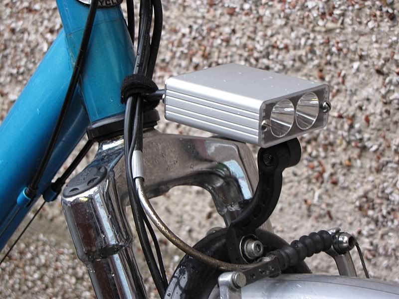 [/IMG]
................. WOW! 😆
Absolutely no comparison with the 2.4W halogen light it replaced. If you've tried the battery light at 500mA .... then that will give you an idea of the amount of light produced ............ did I say ........... WOW? 😆
Controlled by the same Judco switch that used to control the high beam of the twin Smart halogen that I used to have on this old hack bike before I acquired a hub dynamo.
[IMG] 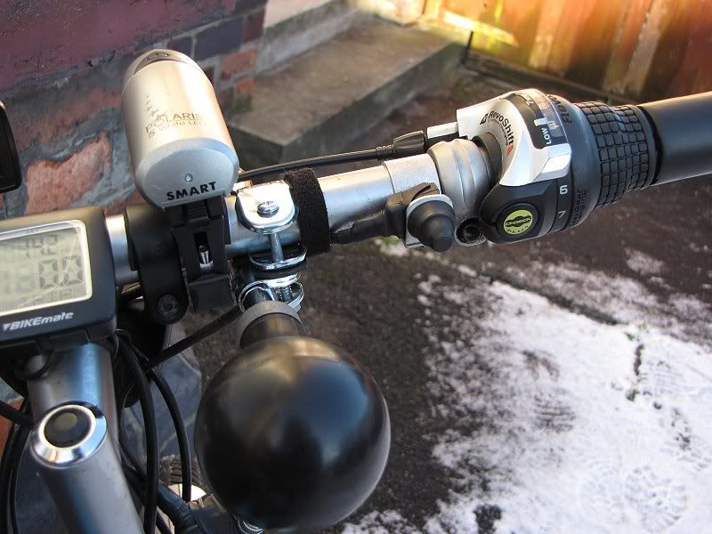 [/IMG]
The old reflector bracket when flipped horizontal instead of vertical was perfect to mount the case via a small bolt tapped through the case and L shaped Led board. This bracket also allowed a little down angle via the notches that these brackets have built into them. It points the main part of the beam at approx 20ft in front of the wheel and the hot spot seems to stretch for a pretty far distance ...... it's near perfect! An added bonus is that it puts a few inches of bright spill on to the top of the silver plastic mudguard to can only act as an additional "see me" from a side angle, because of the shape of the mudguard ..... all helps in traffic!
I took the bike off to an unlit Country Park bike path for some tests. It starts producing light right from the first turn of the wheel when pushing the bike. It's almost as bright at a walking pace as the old 2.4W halogen was at a dawdling cycling pace, but it does flicker! It flickers up to about 4.5mph and smoothes out around that point to produce a cracking amount of steady light .......... plenty to be seen by in traffic and more than enough to ride at a far faster pace than the 4-5 mph I was testing it at!
As I increased the speed up to around 10mph the light just got brighter and I think I could just detect that it was starting to flatten off a little, only a little. Due to doing a nice rear-end slide at a turn on the black ice I spotted too late 😳 and having just managed to get a foot down and kick myself back upright from the slide ... I decided that even with the excellent amount of light available, I would have to be careful with trying a bit more speed.
I got it up to about 19mph (my little helmet light allows quick glances at the speedo) before decided that was enough for the patchy ice conditions in the Park and the light got brighter than at 10mph .... but I suspect that with the Cap values I'm using I'm getting near the peak at 13-15mph .... hard to say for sure on an initial test like this. Suffice to say there was plenty of light.
Distant reflective direction signs lit up nicely from the spill and main centre spot and on the turns I could see that the beam was lighting up trees several 10's of yards away, showing the throw was just like the battery model. The main beam produces a nice enough bright pool that's an ideal width for unlit cycle tracks and canal paths.
I happened across a couple of doggy walkers coming towards me who were attracted to the bike light ...... there was a noticeable synchronised head-turning as I passed by. I decided to turn round and ask them for their opinion if they thought the light was annoyingly bright. They said they definitely noticed it and said that they weren't bothered by it .... and they asked me to do another run passed them .... I happily obliged. They said it was very bright but not annoying .... Perfect!
On the return run from the Park to home, a little five(ish) year old lad spotted me and was hypnotised by the light .... he was heard to utter .... "Cooooooolll" as I passed by ...... great to know it got the approval of the youngster too! 8)
Before I put the bike away, I roped in SWMBO to give her opinion .... she stood in the middle of our averagely lit street as I pedalled off and swung around to aim straight for her on the return run! The result ...... "You just look like a motorbike …. very bright ...only a bit more sparkly than a motorbike!" .... and .... "Not particularly annoying." Job done ... I think! Her parting comment before she scuttled in out of the cold was ........ "The only thing is that the blinkie on the bars is hardly noticeable now, but your helmet light is fine!" Hmmmmm! Another job to think about now!
I’m very happy with this dynamo light! Let me know if I've bored everyone!
nice job and write up bobblehat! 🙂
*wanders off to investigate dynamos*
Was just about to order an exposure light when my mate pointed this diy build out to me,are there any kits left troutie.
Now building the lamp and following the wiring diagrams i have no problems with but all the different drivers and battery options do confuse me,can anyone explain it in a simple way.The more i read the pages of this thread the more my head hurts.
Poo!
Managed to knock the nipple off one of my LEDs 🙁 .... I'm a clumsy oaf.
Mr T, I've emailed you about costs for a replacement LED. Anyone worried about using AAA to fix your LEDs in place, don't worry, I needed a hammer and drift to knock it off the aluminium angle.
Brilliant write up Bobblehat. I just hope Dynamos dont catch on though ! 😆
BigJim, the connectors vary greatly from manufacturer to manufacturer even if they are both 2.5mm some will be a loose fit to an others unless they are really from the same company or high quality.
Hi Piker
Yes I confess the thread and product has morphed a little and I am some what confused with developments .
to try and simplyfy
you will get the right driver from BCT and can use any battery as long as it is over 8 volts and under 24 volts
the case size can handle the full 1 amp drive unless you are stood still on a normal night then you may need to dim it if it gets hot .
Yes I have plenty of all the bits in my side of the light just mail me its in my profile .
Steven yes have plenty of XPGs either on 20 mm stars or 10 mm square boards available .
Flicker You muppet :oops:done the same though .
will pop one in the post tomorrow .
if you want to remove one that is stuck with AAA then heat it up with a hot air gun to ouch temp but not melting solder temps and the star will lift off easyly with out hammers and chisels
Nice one BH see you finally managed to build the dynamo light 😀
I'm amazed that this thread is still going, some great builds out there, just need troutie to start another on how to build the cuboide ( think that's spent right?) Reckon this post need it's own sever/website soon keep up the good work! Feel like building another now! 😉
Just spent an enlivening day looking at synchronous rectifiers and ways of extracting maximum power from a dynamo with minimal loss. Let's just say it isn't as simple as it sounds! The system Bobble uses isn't ideal but it is a heck of a lot simpler than the circuit you'd need to get rid of low speed flicker and optimise the output...
Still, at least between this and looking at the high power drivers I've learned a fairly easy way to implement reverse polarity protection on the input with fairly minimal losses. Only problem there is that I've just bought a few hundred PCBs so that may have to wait until they are all gone.
I think to summarise the build we have pretty much worked out that the 'batteries inside' idea isn't ideal with my drivers as two lithiums give a bit too low a voltage for the LEDs. Most people seem to be cutting the box down and building a lights + driver unit which is connected to an external battery. This battery needs to be 8 NiMH cells or 3 lithiums as a minimum. The driver allows you to switch between full power, 40% power and off without having to disconnect the battery.
Troutie - will be in touch over LED costs.
Wonder if it's worth starting a new thread with a summary of what you need, where to buy it and how to do it but point anyone here for discussions?
Troutie paypal gift sent,now for a suitable driver.New thread is a good idea.BCT what do i need from you a driver switch and resister or is the resister built in now.
Resistor built in on all drivers now giving 40% dim mode. You can alter this with your own resistor though. I have switches with a waterproof boot and also do power socket / plug with lead. Kits of the lot are £8 each plus £1 postage. Also have a few 2, 3 and 4 way 18650 holders left.
been a bit of a discusion here on dyno circuits http://www.candlepowerforums.com/vb/showthread.php?179805-Dynamo-LED-Driver-Circuit-PCB-available
all gobbledygook to me
Lipseal .
the cuboid is dead easy and I will if needed supply the basic bits of aluminium rough machined for finishing am building another so will document it better and could use BCTs upcoming boost driver and a 4 cell 7.4 volt battery pack
BCT is it a gift to the email in your profile for paypal.
The basics are easy, getting that bit extra is the hard part. Dynamos output AC at a frequency which varies with speed. The simple way to convert AC to DC is to use a bridge rectifier but you then lose around 1.5V which on a 6V supply is significant. You can reduce this by using better diodes but you can't get it much below 1V. You can replace the diodes in the bridge with mosfet transistors but the tricky part then comes with turning them on in at the correct time to prevent current flowing the wrong way and creating smoke.
The next stage beyond what they are doing in that thread is being able to store some of the generated power when it isn't needed and use that to supplement the dynamo at low speed and when there isn't any stored to eeke out what you can get from the dynamo to give a steady albeit dim light. This involves all sorts of fun stuff like monitoring how much charge is stored, how much is being generated and working out how to balance to two, plus things like reducing the load on the dynamo when you don't need it generating power. Something I'd love to get my teeth in to but I suspect it would be too much to take on at the moment! Maybe for next winter...
(Piker - Yes, payment to the address in the email)
Got me thinking now, I wonder if say 4 of these:
http://uk.farnell.com/jsp/search/productdetail.jsp?id=1778025&Ntt=1778025
could be wangled in to something like a P7 reflector... I think two may go in a regina with a bit of modification... Run at 50mA you get about 15 lumens each, not a massive amount but may be enough for basic visibility (including being seen) then have a single XPG as a 'boost' light depending on enough power being stored or generated.
Supercaps would be an option for storage but I suspect something like a CR123 would be more economical, not sure how fast it could be charged though. Those little NiMH cells (3.6V few hundred mAh) would be ideal but they can't take or give much current.
Keep me in the loop regarding the cuboid, if you don't mind. My build is still going strong and it's been on a few wet and muddy/icey rides well impressed.