Home › Forums › Bike Forum › Lacing a fat bike rim
- This topic has 42 replies, 16 voices, and was last updated 9 years ago by Laggingbehind.
-
Lacing a fat bike rim
-
LaggingbehindFree MemberPosted 9 years ago
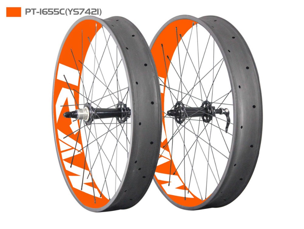
I have a 32 hole Hope Fasno hub and a 32 hole rim where the holes on the rim are parallel to each other… Anybody ever laced this combination, if so what pattern did you use……
m0rkFree MemberPosted 9 years agoSo 64 holes?
My front is laced so the left side goes to the left row, right to the right
My rear is offset though, so all on the left row (that’s why they have the option I guess)
 scotroutesFull MemberPosted 9 years ago
Just go 3-cross as per normal? I’m struggling to understand why you’d think any different. What rim is it?
LaggingbehindFree MemberPosted 9 years agoThe problem………according to the wheel builder I gave them to says its a problem because the holes are parallel but the holes on the hub (a Hope Fatsno) are off set as normal.
AlasdairMcFree MemberPosted 9 years agoYou only use half the holes on a fat rim, so you’ll have 32 holes unused, opposite holes that are used by spokes…
scotroutesFull MemberPosted 9 years agoTell you what. If your “wheelbuilder” doesn’t know the answer to the question, take it to someone who does.
LaggingbehindFree MemberPosted 9 years agoYou only use half the holes on a fat rim, so you’ll have 32 holes unused, opposite holes that are used by spokes…
It only has 32 holes in total
LaggingbehindFree MemberPosted 9 years agoTell you what. If your “wheelbuilder” doesn’t know the answer to the question, take it to someone who does.
Trying to find another is turning out to be a problem with the hub / rim combo I have…….the reason for the thread is to try and find out if it’s possible
LaggingbehindFree MemberPosted 9 years agoThe holes on the rim are parallel to what? What rim is it?
To each other, ie 2 parallel spoke holes every other cutout
cannondalekingFree MemberPosted 9 years agoIt is possible I’ve built a few of them now for customers you can build them up standard 3x but the spoke lenghts are different to a standard offset due to the rim drilling or 2 spoke parallel which is a little more fun to build.
AndyFull MemberPosted 9 years agoSo effectively 16 pairs of holes around the circumference of the rim? Intrigued to the make of rim 😕
shermer75Free MemberPosted 9 years agoI googled for an image and this came up, I think it’s the right one:
 shermer75Free MemberPosted 9 years ago
So I haven’t actually tried it so this may not work, but in my head feel like you can still do a 3- or 2- cross by having all the inbound spokes going to alternate pairs of holes (left flange going to left hole, right flange going to the adjacent right hand hole), then doing the same with the outbound. Or is the main issue calculating the spoke length? Because that would be the bit I’d struggle with the most…
shermer75Free MemberPosted 9 years agoThat would look amazing! Still not sure how to calculate spoke lengths though…
whitestoneFree MemberPosted 9 years agoI think I know what the OP is getting at.
On a standard width rim, the spoke holes are in-line: left, right, left, right. The corresponding holes in the hub flanges are offset when you look at the hub along the line of the axle to account for this. I.e. one flange has been rotated half the angle between spokes.
On the linked fat rim the spoke holes for left and right are both at the same point on the circumference (what the OP calls “parallel”)- 12 o’clock; half twelve; etc. Unless the hub has the flanges similarly set up, i.e. no offset, then you’ll need different length spokes for each side.
bencooperFree MemberPosted 9 years agoIt’s too early in the morning to think about this seriously, but isn’t left flange to left hole etc the wrong way to do it? A normal wheel is strong because there’s a triangle between the rim and the two flanges, doing left-left and right-right turns that into a rectangle. Isn’t left-right and right-left better for lateral strength?
whitestoneFree MemberPosted 9 years agoYou have to set (bend) the outbound spokes at the elbow for a normal rim, doing so for a fat rim would need quite a bit of bend if you were going left flange to right side of rim and vice-versa. Looking at shots of fat bikes they all seem to be laced left-left, right-right. It’s a compromise but presumably it’s been thought about.
Early morning fuddle: no need for different spoke lengths for either side – rotate the hub to split the difference. 😳
bencooperFree MemberPosted 9 years agoPossibly it’s that fat bikes never go fast enough for wheel lateral strength to be an issue 😀
LaggingbehindFree MemberPosted 9 years agoI think I know what the OP is getting at.
On a standard width rim, the spoke holes are in-line: left, right, left, right. The corresponding holes in the hub flanges are offset when you look at the hub along the line of the axle to account for this. I.e. one flange has been rotated half the angle between spokes.
On the linked fat rim the spoke holes for left and right are both at the same point on the circumference (what the OP calls “parallel”)- 12 o’clock; half twelve; etc. Unless the hub has the flanges similarly set up, i.e. no offset, then you’ll need different length spokes for each side.
leegeeFull MemberPosted 9 years agoBlayne, I found this

Any help.
More here.
http://traildevils.ch/Market/b58043691fe3c6662d7f08d22ef047eectznsmithFree MemberPosted 9 years agoI’ve never done this but this is my guess based on my experience and knowledge of the theory. All the hail the internet! 😉
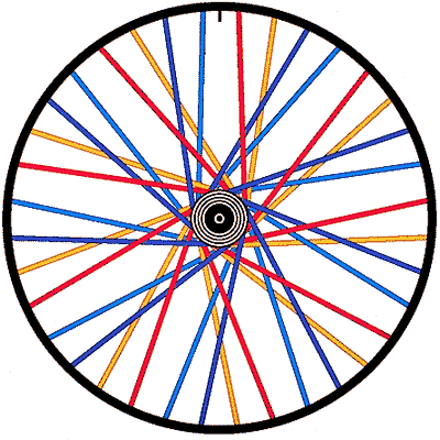
This is a standard wheel viewed from the drive side.

If the hub flanges are not central on the axle then the drive side should be as above but the non-drive side will be rotated anti-clockwise so the yellow/red and blue/blue spokes hit the rim at the same point. This means the yellow spokes will be longer and the blue shorter on the non-drive side. Which would mean 2 different spoke lengths on the non-drive side.
If the hub flanges are central on the axle then it’s possibly best to split the difference so the drive side rotates clockwise a bit and the non-drive side anti-clockwise from the ‘norm’. This should mean 2 different spoke lengths on each side of the hub but they should be the same each side (I think!).
Why this won’t work:
1) With 2 different spoke lengths on the same side of the hub, can you get the tension right?2) Depending on the distance of the spoke hole from the edge of the flange/angle of spoke out of the hole and then bent over the flange – there may be too much flange in the way when you rotate the hub for some of the spokes to easily exit the outer hole and reach the rim. The large rim width helps you here though.
C’mon STW pull that apart. 🙂
Another option, lace the non-drive side 2 cross? Would this help matters or improve it? (my brain can’t visualise that)
I’m not suprised your wheelbuilder said no, this would melt anyones brain for correct spoke length before you even got near actually building it!
ctznsmithFree MemberPosted 9 years agoActually in option 2 wouldn’t all spokes be the same length?
You could sit down and do it by trial and error but it’s going to take a lot of time unless you get lucky!
P.s. Whoever designed that rim needs shooting.
cannondalekingFree MemberPosted 9 years agoSpoke length is easy to work out ctznsmith is only math lol pie R cubed easy stuff really. To OP if your wheel builder won’t do it drop me an email its in my profile
bedmakerFull MemberPosted 9 years agoThat’s a really odd way to drill a rim!
I’d send it back and get a Rolling Darryl/Halo/Marge lite ar something a bit less freakish.
Or drill a new hole on alternate sides of each blank bit.I can’t see how you can build it without 3 differing spoke lengths, and the ensuing nightmare tensioning would bring.
A normal wheel is strong because there’s a triangle between the rim and the two flanges, doing left-left and right-right turns that into a rectangle. Isn’t left-right and right-left better for lateral strength?
Like a BMW motorbike?
That’s exactly what I thought, so I did it. Don’t ask me why, or how to explain it, but the wheel was more noodly than just the bare rim on it’s own. I switched to left-left and right-right and it has been perfect ever since.And you’re right, fatbikes don’t go fast enough to break wheels, they just melt occasionally with reflected light from the enormous grin fatbike owners constantly wear.. FACT.
bgrunesFree MemberPosted 9 years agoThis is one of the members on the fat bike forum, appears successful. Be interested in the outcome from this thread as I’ve just bought the same rims!
 shermer75Free MemberPosted 9 years ago
Spoke length is easy to work out ctznsmith is only math lol pie R cubed
In my head this would only work if the spokes are laced radially. Or am I completely wrong?
shermer75Free MemberPosted 9 years agoThis is one of the members on the fat bike forum,
This is how I’d go about it. Not sure why it would need more than 2 spoke lengths, but I may be missing something very obvious…
ctznsmithFree MemberPosted 9 years agoThis is how I’d go about it. Not sure why it would need more than 2 spoke lengths, but I may be missing something very obvious…
Looking at it in practice I’m not sure it will need more than 2 spoke lengths, possibly one if the wheel has little or no dish.
Also decided that the 1st part of my previous post/suggestion is wrong, the tensions would be all over the shop. Rotate the hub slightly and split the difference is the way to go. As someone said before me!
cynic-alFree MemberPosted 9 years agoI think it’s bound to need 2+ lengths, which could easily be worked out trial and error lacing up 12 spokes.
It beggars belief to me, how many self entitled “wheel builders” can’t do this.
cannondalekingFree MemberPosted 9 years agoClynic-al is right easy enough to build any wheel builder that can’t build one of these shouldn’t be building them.
The topic ‘Lacing a fat bike rim’ is closed to new replies.

