UPDATE: Reviews section refreshed, redesigned, searchable: Go take a look
Mr Trout, did you find the LED's center themselves on the PCB with your DIY reflow . . . just thinking from an optical alignment POV . . .
Fd
Quick q. about heatsinking - does the heatsink actually need to touch the case, or is it sufficient to just draw heat away from the back of the pcb and into the case? I ask because they had some neat little self adhesive RAM heatsinks in Maplins which look like they'd be great, but they won't touch the case.
These - http://www.maplin.co.uk/Module.aspx?ModuleNo=98850
TIA
IMHO they should touch the case. that way the heat from the LED's transfer into the heatsink and then from that into the case.
I suppose the term heatsink is not actually correct, more of a heat transfer block.
Furgusd
yes if you look real close at about 4 mins 30 you see the top of the 3 leds settle in and twist around a little though I did try and get them in the right place before I started the heatgun .
it was a worry but the optic fitted perfectly after .
The heatsink needs to be in contact with the rear of the LED board and the case, you are trying to get heat away from the LED's and out of the case, not into the air in the case . . . given the cheap ebay heatsink, why do anything else . . .
Ref wiring diag, here's one for what is being discussed I believe . . . it's critical you don't screw up and mix up the connections - applying the wrong voltage to the wrong connection will fry the unit . . .
[img]  [/img]
Also for people doing this it's worthwhile considering some constructions tips . . . insulating the regulator is probably best done using some heatshrink tubing . . . you can get it on ebay, you're looking for something like 20mm diameter with a 2:1 shrink ratio . . . or 25mm with 3:1 . . . would be worth someone buying a metre or so and chopping it down for others, you only need say 30mm length . . . very neat and very strong compared to insulating tape for example which is really pretty useless . . . ideal for rattling around in the back of the can . . .
[img] 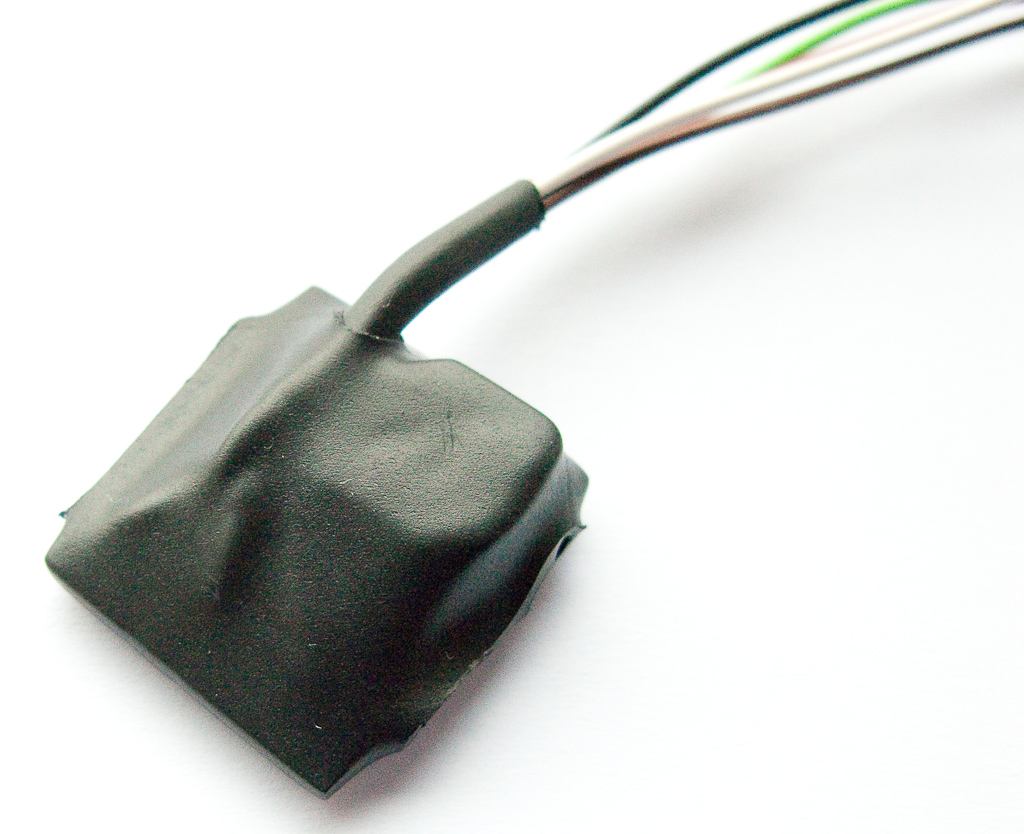 [/img]
Cheers all
there is also the option with a 3 pos switch to short direct the neg to A missing out the resistor as a soft off too
cheers fergusd
saves me doing one.
and a good tip about the heatsink. it is a much better solution than insulation tape.
I just didn't have the right size.
Yup,I didn't include the soft off option as the standard lumi switch is only 2 pos 😉 . . . bargain basement mode 😉
This guy sells heatshrink at semi decent prices for smallish quantities . . .
Fd
Thanks very much FergusD and Chucky. I received a couple of drivers from that nice chap on eBay yesterday, and the instructions (plus the circuit diagram above) make everything clear. I think I might run the 5W driver with a 100k resistor switchable in. That way I can run with a low mode of about 330mA and a high of 970mA. I figure that I'll mostly use this unit for road commuting. In traffic around town the low setting should be enough, but once I get out onto the country lanes with lots of airflow then I can opt for uber-bright. Might convert a second head unit later for offroad use. I also saw those RAM heat sinks and similar in Maplin. I'm wondering if it might be possible to mount something like that on the outside of the can, though obviously the heat sinks have flat bottoms, so would need some careful mounting to make sure that the heat flows nicely.
If you want to mount a heatsink on the outside of the can, have a look on eBay for RC car motor heatsinks, one of them - I think the 520 size - is an exact match for the lumicycle halogen case. It's a semi-cylindrical finned thing. I stuck mine on with heat transfer tape and it warms up fast, which suggests that it's working and dissipating heat.
It is all about heat transfer - there's no point in sticking a heat sink inside the can unless it can transfer the heat into the lamp body and simply having an interference fit between the LEDs and the lamp isn't good enough, you need some sort of heat transfer medium as well.
Sorry if that's all blindingly obvious, but if the heat has no way of getting to the outside world, then it will slowly bake your expensive LEDs. The heatsink is just increasing the effective surface area to lose heat from, but if it's simply heating the air inside the can, it's not going to be very effective.
Something like [url= http://cgi.ebay.co.uk/RC-540-Motor-Upgrade-Vented-Alloy-Heat-Sink-heatsink-B_W0QQitemZ200374783340QQcmdZViewItemQQptZUK_ToysGames_RadioControlled_JN?hash=item2ea7448d6c ]this[/url] btw
That looks ace! Might order one and give it a go. Cheers BWD.
No worries. My only concern would be landing on top of it on my chin, but it hasn't happened yet, touch wood 😕
I don't reckon the chances of that are very high. I'm pretty sure that I've never had any kind of face-to-bars impact. I reckon that'd be quite hard to do unless the bars snapped or something. Also, I'm hoping that my light will look a bit like a robotic baby hedgehog with the sun shining out of its a$$!
squeeky you ned to order thesehttp://www.cutter.com.au/proddetail.php?prod=cut781
Choose 3 way narrow for XPG
and
http://www.cutter.com.au/products.php?cat=Cree (plus) XPG
for some reason it won't put the plus sign in the link
choose R4 from the first pull down and cutter-XPGMR11T from the 2nd pull down.
Looking to order these, but slightly confused as to what I'm supposed to be ordering.
The cart shows the narrow optic which is correct, but I seem to have one cree xlamp xpg led at 5.95, the XPGWHT-L1-0000-00G51 R4 Bin and the Cutter-XPGMR11T.
Am I correct in thinking I will get a triple XPG mounted on a board?
Yep the Cutter-XPGMR11T is triple XPG mounted on a MR11 PCB
Er yeah the Cutter shopping cart is crap...I'm sure what u have ordered will be XPGx3 If u amend the XPG bin qty to 3, the total shoots up to 90 odd dollars..GULP!
Thanks for that, I thought I was being a bit dim there for a moment. 😳 I have ordered only one!
Woohoo! My LEDs and optics arrived from Oz today. I ordered XP-G optics, but they are listed on the invoice as XR-E ones, so I guess there are still no XP-G-specific ones. Ah well, I got a narrow and a medium so I'll just try both and see how they work.
let us know how the build goes gray
and piccies
I certainly will, though I'm waiting for a couple of bits to arrive from Maplin (three way switch, thermal tape, resistors) before I can make a start, and I'm off on holiday for a week from Tuesday, so it may not be until nearly Christmas by the time I get a chance.
Do you use anything to hold the feet of the optic to the LED PCB? If the wires etc. from behind are nice and springy and a tightish fit then I can imagine it might all sit happily in place of its own accord, but I was wondering about a little blob of silicone or something else (reversible, to enable optic swapping) on each foot to hold the LED board in where it's supposed to be relative to the optic.
I don't use anything. As the bezel on the lumi can hold it in place. but i think a couple of small blobs of silicon won't hurt.
I file the legs down a little so that they are not quite as deep as the LED PCB (you will notice they protude out the back of the PCB) . . . then use some rubber rienforced superglue to hold them in place on the PCB . . . you don't need to but it makes handling easier . . . it's always possible to remove it if required . . . only the smallest quantity is required . . .
I've been playing with the 970mA driver for a standard can conversion using XP-G triples . . .
The current regulator itself doesn't overheat at 970mA with an 11cell NiMh and running long term . . . good news as it's mentioned it may need heat sinking . . . but I've been struggling to get the 1/2 power mode working with the suggested resistor values . . . more experimentation needed . . .
Also waiting on some hedgehog heatsinks arriving from the US which I think will give a 1000 lumen helmet mount hog lamp . . . I think with the extra heatsink it will be fine in moving air . . .
Fd
All the bits have now arrived. Hope to get the light done sometime next week...
Just completed my Lumi can conversion:
[img]  [/img]
Comparison to my previous helmet light, a Hope HID (first picture)
[img]  [/img]
[img]  [/img]
(apologies for the shakey camera work)
I used the MR11 triple MCPCB with XPG-R4 LEDs from Cutter (I used R4s cos R5s were out of stock) and a Ledil XRE optic also from Cutter.
Note to Gray above, XPG optics are available but just not from Cutter yet. The Ledil site lists them and has links to datasheets etc. Problem is getting hold of them. I spoke to a couple of UK agents and they would have to order minimum quantities etc.
The LEDs are driven by a bFlex driver, again from Cutter, it's dearer than the ones listed on Ebay but much more versatile and programmable.
I also used the RC traction control hub as in the original post for the internal heatsink, which worked well.
I had also hit upon the RC motor heatsink idea and bought one from the States on Ebay, however BWDs suggestion was much neater so I used that instead (thanks BWD). I haven't yet had it running for more than 5-10 mins or so at full tilt (1000mA), however so far it doesn't seem to be getting red hot.
I can also recommend the heatshrink idea for sealing the driver board, much easier than insulation tape.
Other tips you might want to consider:
- to increase the amount of space inside the can I sourced an alternative toggle switch from Farnell, order code 957-5731. This is a momentary on and has a much smaller switch body. Also, I removed the plastic spacer so it sat flush with the inside of the can. You still need a spacer on the outside if you use the weather proof switch cover, I used a small length of Camelbac hose to provide a decent seal.
- This isn't necessary but I changed the power connection to a three pin Brad Harrison/Woodhead type as used on the original Hope, then made up a short adaptor lead from the Lumi connector to a three pin. This means I can use either the Lumi battery or the Hope one. This connector is also smaller than the original Lumi one helping to save space.
Thanks to all who have posted, this has been a very interesting (and so far successful) project. I'm currently waiting on a custom CNC housing to be made (should be done Monday) so I can fit all the components to make a x7 XPG R5 bar light (that's nearly 2500 lumens folks!)
Cheers
poisonspider
nice 😉
Fd
looks good PS
that switch will work with the Bflex but for the ebay drivers it will have to be a lockable switch, not a momentary one.
I've just ordered some of that heatshrink, it does look much better than insulation tape.
the difference between the HID and your conversion is massive 😆
Are the XPG specif optics the same size as the cutters?
Externally the XPG opitics are exactly the same as the XPE.
Link to XPG Cute 3 datasheet:
[url= http://www.ledil.com/datasheets/DataSheet_Cute-3-XP-G.pdf ]http://www.ledil.com/datasheets/DataSheet_Cute-3-XP-G.pdf[/url]
Link to XPE Cute 3 datasheet:
[url= http://www.ledil.com/datasheets/DataSheet_Cute-3-XP.pdf ]http://www.ledil.com/datasheets/DataSheet_Cute-3-XP.pdf[/url]
I originally wanted a narrow spot but as Trout mentioned above the XPG adds 8deg to the XPE optic, which has actually worked out really well, so the XPE optic is fine.
Simple retrofit when the new optics become available 😉
Fd
Finished doing mine today with the XPG's and the other parts recommended by Chucky. Took about 1 1/2 hrs, most of which was spent trying to get the parts into the can. Apart from getting heatsink paste EVERYWHERE I had no problems at all. Am yet to give it an off-road test but the light seems way brighter than my 20W halogen. Many Thanks for the easy to follow guidelines!
My pleasure.
The cutter stuff has just arrived for you guys waiting.
I have not opened up the package yet, but it looks like we got away with no VAT or Import tax 😀
I'll try and get the stuff sorted in the next few days and posted out at the weekend at the latest.
Will also do my Lumi HID conversion with photo's and a detailed how to as well, for those of you who asked for it.
cheers
Chuck
Cool nice work sir - that's the best news in ages.
I guess these XPGs are all cool white? Be interested to know how you folks get on with them from a perceived contrast point of view.
i'm confused, never having anything to do with elec-tricks before, but i'm also intrigued AND i have a housemate with a soldering iron.
i've two lumi halogen cans and a 14.4v (i think) endurance battery (the biggest one lumi offered at the time of buying (~2 years ago)).
the DRIVER does what exactly? controls the amount of power reaching the LEDs so that they don't blow? does it have to be the same one that Chucky listed easrly on? will [url= http://stores.shop.ebay.de/PCB-Components__W0QQ_armrsZ1 ]700mA, 1000mA or 1400mA (click here)[/url] be ok?
judging by some of the pics (sequence of three on the first page) these things are silly bright. i find 35w/38 deg halogen is enough for most riding.
warm white, cold white, XRE, XPG. what should one order? also, narrow or medium angle lens? is the narrow enough when using the XPG bulbs?
many thanks
J
You guys all have mail reference me posting the stuff out. (after you have paid of course) 😆
Alpin, your battery is probably a 14.8volt one.
The drivers you have linked to as far as I can see are for up to 6volt.
The ones I used are for up to 24volt.
I have not tried an XPG yet, but looking at the ones that have come with this order from cutter, my view would be a triple XPG R4 with a narrow optic.
The mediums are a bit too wide for me.
This would give in the order of about 700 plus lumens (if not a bit more)
Chucky
The R4 has a nominal output of 130 lm, driven at 1000mA it's 2.5 times that, giving 325 lm.
x3 should give 975 lm. (an XPG R5 would be 1042 lm)
These are datasheet numbers so are to some degree theoretical, I'm not sure how to calculate/measure losses in the system to get the real figure though.
Only taking into account the lumen measurement of a light is like only taking into account the BHP figure of a car. A datasheet lumen measure will only tell you the theoretical total maximum light output [i]according to the manufacturers of the LED units[/i].
Much more important, IMHO, is the colour temperature and beam pattern, the latter determining the illuminance (Lux) figure, or the amount of light per square metre. Beam pattern preferences will also vary from rider to rider, and I reckon flexibility is the key.
Great Thread.
All 3 factors have importance. But, so long as I've a fair few lumens, then I can suffer a warmer than prefect colour temp and less than optimal beam pattern. ( I prefer cool light, flood on the bars, spot on the helmet )
We're compromised by having to source off the shelf parts.
I like this conversion and I'm looking forward to seeing more beam shots, before/after and end result pictures of the build people will be doing.
🙂
L.
The spectral intensity of sunlight peaks at about 600nm wavelength with a smooth curve at either end(visbile light being around 400nm to 700nm ish). The ideal output for a bike light would be a similar profile giving 'daylight' feel to it. Unfortunenately I don't think that's possible with LEDs.
The XPG has a significant spike at about 450nm, the blue end of the spectrum, and relatively little at the 600nm end. This is why they have a bluey, ice white kind of colour. In my experience can this can lead to contrast issues, particularly with a helmet light on its own.
Has anyone tried a multi LED setup with differing BIN lamps to try and construct a sunlight like spectrum? Maybe that should be the next project 😕
bloody hell lad's, this is getting a bit techy.
It's amazing how Wikipedia can make an expert out of anyone! 😉
I'd be happier if you could get LED's that match the 'look' of the light from the halogen lumi's. I find the warmer light helps make out details and stuff. Can't really describe why.
That is my only concern about doing the conversion.
Was totting up the cost of it all last night and it's looking like £40 or so with the heatsinks & stuff.
Will get round to ordering it at some point. Need to get a soldering iron as well from somewhere. The other half is excellent at soldering so no worries there.
The ebay bloke doesn't have any of the drivers at the moment; he has the screw fitting one (rather than solder) but presumably that's loads bigger.
Cutter do a multi colour temp triple board (with three different tint LEDs on the same board)
Its all to do with colour rendering, depth perception of colour temperature & contrast ratios.
Not to mention that natural light comes from above & bike lights from your bike (so the angle of reflection becomes an issue)
Yeah, sunlight is very 'orange', though nothing like as orange as tungsten filament lighting (old school incandescent lightbulbs).
At low light levels, the rods in our retinas are much more sensitive than the cones (the 'colour receptors'). The peak of the rod response is around 500nm, a blue-ish-green colour, which unfortunately is something of a gap in the available spectrum of both 'white' LEDs of all colour temperatures and monochromatic colour LEDs. At least one light design on Instructables advocates using cyan or green LEDs close to the peak rod response in order to get the best visual response for the actual light output. Researching this a bit further, I found that many people who tried this simply found that it made everything look a bit too weird to be usable.
Interesting thread on colour rendition [url= http://forums.mtbr.com/showthread.php?t=485410 ]here[/url] including using two different Cree MCE colour bin LED types to get a better compromise of overall light colour. Also, comments from one guy who said he used a red LED for jogging and didn't notice the colour after a few minutes until he got back into the vicinity of white-ish light.