UPDATE: Reviews section refreshed, redesigned, searchable: Go take a look
A bit confused as to ahich XRG to order as there doesn't seem to be an option for the triple mounted board. Is the bin R4 and then the board the MR11T?
A bit confused as to which XPG to order as there doesn't seem to be an option for the triple mounted board. Is the bin R4 and then the board the MR11T?
A bit of a numpty question...when ordering the XPG LEDs from cutter do I need to place 3 in the quantity box (5.95 dollars each) along with the MR11T board and the optic or does the board (22 dollars)include the LED's mounted on it?
squeeky you ned to order these
[url] http://www.cutter.com.au/proddetail.php?prod=cut781 [/url]
Choose 3 way narrow for XPG
and
http://www.cutter.com.au/products.php?cat=Cree (plus) XPG
for some reason it won't put the plus sign in the link
choose R4 from the first pull down and cutter-XPGMR11T from the 2nd pull down.
Troutie i'll mail you tonight ref those LED's
just a small point troutie you mentioned an 8 deg increase when using a XRE optic does this angle expansion happen with the specific XPG optics?
Thanks! Now all ordered and I've already received the driver. I'll have to dig the soldering iron out...
Chucky, did you receive my mail yesterday??
yip conespanner, and replied as well.
I hope the XPG optic issue is sorted... Brilliant thread Chucky, nearly as much interest as the toutastic troutie thread!
PS just responded to ur email too 🙂
Chucky - YGM 🙂
Chucky
the optic angles there are as yet no dedicated xpg optics just rebadged XPE optics and these are showing a much wider beam I mentioned it so you did not waste money on wide optics .
with the narrow optic you will still have a great light .
The Xpg optics should start appearing soon
The Xpg optics should start appearing soon
are the ones on the site XRE's then?
they are listed as XPG specific.
Chucky - did you get my email? Not sure they're leaving my outbox!!
Cheers
let me know when you are going to order as well - you got my number e-mail etc
yip got it woody.
tomorrow night John is when the order goes in.
What do you require?
😀
whatever I need to convert that lamp please
Was that a bit too technical for you?
e-mailed ya
righto Johnny. Speak to you tomorrow.
Update Gentlemen.
Just managed to sort the 200k resistor out. Dismantled the unit I made up and just basically soldered the resistor as per instructions that came with the driver.
It works a treat.
Drops the current draw down to 335ma.
I will have a go at fitting it properly over the weekend and post some more 'how to' piccies up.
As have mentioned earlier this mod should alleviate all of the concern over the heat. Just switch the lamp onto 1/2 setting when stationary for long periods.
'Simples'
[img]  [/img]
Excellent! very worthwhile as there is no thermal cutout with the ebay drivers
Aye . . . remember, however, that things (well the LED's) will still work at 150C . . . so while thermal shutdown is nice to have it may not be necessary . . .
A ever . . . there is no substitute for testing . . . or simulation if you can afford it 😉
Fd
Chucky
lumi orders in including you bit.
N
nice photoshop of Archie 😆
Nockmeister
The -thermal protection is controled be the best multitasking computer ever
whilst riding along should be no issues but if you forget to dim and stand around too long on full they will get hotter and the as they get hotter the lumens drop and if the light turn blueish then you are near the killing zone and the light will be melting its way through your helmet in mounted there.
Those drivers from teapot are solid and work well
I never knew he was called archie 😳
Cheers Nige
he's not. Junkyard was being sarcy. BTW John is that your waterbottle cluttering up my garage?
here is Archie its our dog. who is half dog half kangaroo
[img]  [/img]
Cheers for the pointer to teapot. those drivers are spot on.
I'll have those LED's BTW. I'll mail you back for payment detials etc.
ta again
Dave
wondered where that was SIS one with water in it then yes
It's 10:45 on a Friday should you not be out 'clubbin'?
Many years ago yes but today nothing stronger than Lemsip 🙁
manflu?
Well done guys, This is what forums are all about.
You want to organize a singletrack 'homebrew light' nightride 8)
not even that just sneezing/ cold --- might just pull through.
Best do riding lakes Sunday you free?
Just completed the resistor mod and it works a treat
[b]Job 1[/b]
I soldered the very small resistor in line with two wire end like this
[img] 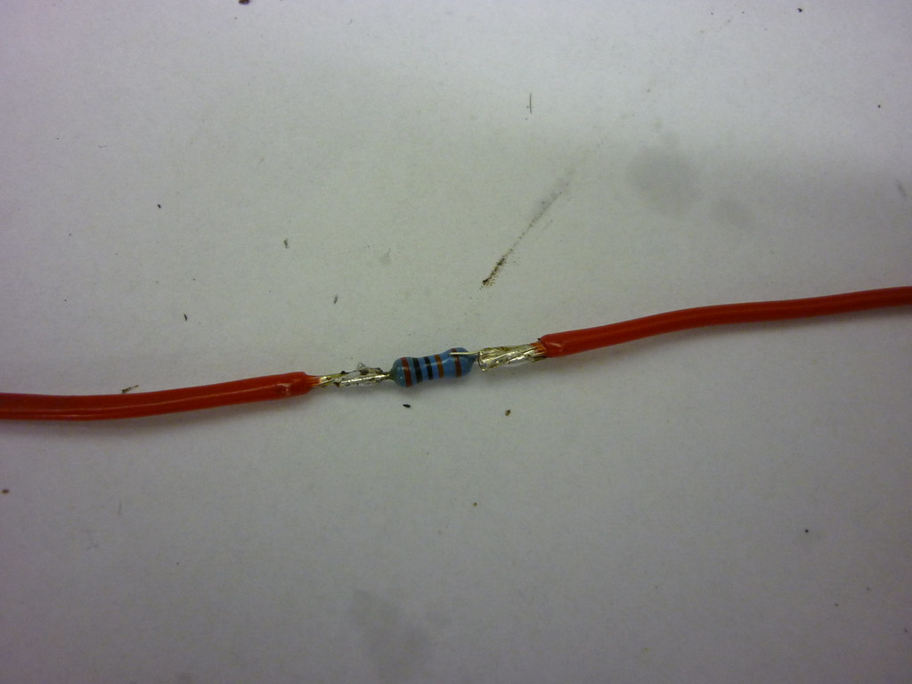 [/img]
[b]Job 2[/b]
Then you need a two postion switch (not sure if the std lumi is or not.)
I got mine from Maplin
[url] http://www.maplin.co.uk/Module.aspx?ModuleNo=2341 [/url]
Type A
The instructions that come with the driver say you need to switch the resistor 'in' to get 1/2 power and switch 'out' to run the full 670ma.
The solder connections when complete look like this
[img] 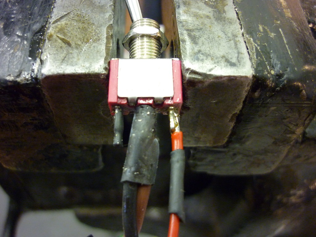 [/img]
The connections from the input socket to the switch and from the switch to the board (the black and brown ones)provide a non interupted circuit when the resistor is switched 'out' Ie as though the resistor is not there.
[b]Job3[/b]
then solder the resistor to 'A' on the board and .
[img] 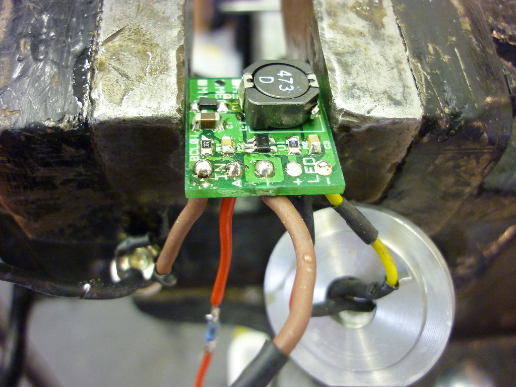 [/img]
The best way to ensure the whole thing fits in is to have the longer length of the driver 'across' the lumi can. This will give about 2-3mm more room.
The finished set-up (before trial installation) looks like this
[img] 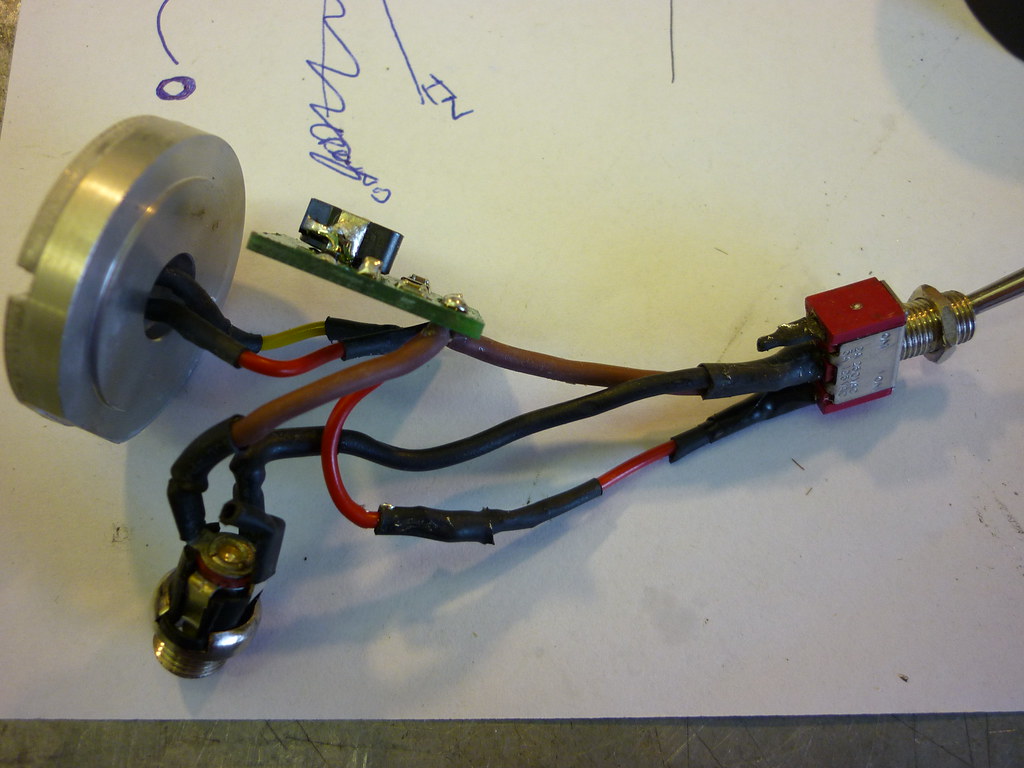 [/img]
As with the original conversion at the front of this post I find it much better to try the whole thing first and get all the wires 'formed' and shaped the commit to using heattransfer paste and do the final assembly.
Don't forget to insulate [b]EVERYTHING[/b] before powering up, this includes the resistor. This will stop anything shorting as it is quite a tight fit.
Hope this makes sense
cheers
Chuck
Hi Chuck,
I don't really get how you've wired it up - probably being dim, but I don't suppose you could perhaps scribble down a rough circuit diagram to explain pretty please? Have you configured it so that the two switch positions are on-low and on-high, so that you have to unplug the power lead to turn the light off? I have a driver but no instructions mentioning what the resistor should be connected to in order to lower the drive current. I was planning to add a second switch so that I have one for power on/off and one for current high/low. Cheers - really appreciate all the info.
Forgot to add, an alternative set-up for the resistor could be to glue it onto the switch body. That way it will be out of the way, and not 'stiffen' up the wire from the board to the switch. This method may help the wire bend easier.
Gray
.so that you have to unplug the power lead to turn the light off
yip you do have to unplug the power lead.
One option is that at Maplin they do on-off-on switch ie centre off and either way on.
The way I have wired it is switch one way for full power and switch the other way for 1/2 power.
The resistor is wired form A on the driver board to a 'outer' tab on the switch. It does not matter which outer tab you wire it to.
I'll try and do a wiring diagram and post later.
May take a day or so.
Im really keen on getting this upgrade done (as soon as the credit card turns up..shhh dont tell Mrs B)
Im getting a bit losts now with whats being ordered.
Chucky can I email you for a definative list or do you have spares of the kit that I can get direct from you?
mail me and we will see what we can sort out.
e mails in profile
Have you sent the order in yet Chucky? 🙂
yip order is in.
Just a point, a took up the registered mail. It was about £40 but considering the shipping was free due to the size of the order and there is about 16 of us (therefore works out £2.50ish each).I thought it was prudent to be able to track the stuff.
Plus thats nearly £500 on my credit card, so I would rather have a way of making sure it arrives for obvious reasons.
CRIPES thats a large order... 😀
I know
I've got a spreadsheet and everything 😆
I hope you lot don't change your minds or i'll end up with more lights than troutie.
BTW I could not find your bare XPG's anywhere nockmeister. they seem to be all mounted on PCB's. (probably not looking in the right place)
sorry but i ended up missing them off the order
can you send me a link and i'll try and sort it by seeing if they will add it on.
sorry
Dave
Nockmeister
sorry if you are a wizz at electronics then ignore this .
but do you realise the size of bare XPGs and how difficult they will be to solder too .my advise would be to get them on 10 mm square boards and if you do want them bare then remove from board
[IMG]  [/IMG]
my rainy sunday project was to remove 3 damaged leds and replace using a cobbled up reflow method I was dead nervous but had a successfull outcome
see vid
[url]
Wo I can't wait!
Hahahaha sorry trout, i meant the monetary amount of the order, 500quid on semiconductors is quite a lot! I work in discrete semiconductors so i know all about small packages 😉
er i'm going for pcb mounted LEDs as my soldering skills are non existant!! I have a buddy who wants a couple to play with in other projects...
Chucky - if you want some money now to cover the current cost, just let me know. We can sort out tax/duty etc later.
Cheers for sorting this out 😀
Your alright woody, i'll wait till everything arrives and we now the full cost.
Thanks for the offer.
Cheers for sorting this out
My pleasure
Chucky
Leds in the post this afternoon .
cheers trout