Chucky those leds are still available if you want them I just had a mail from mikey saying he didnt want them
Chucky,
I've sent you a mail regards purchasing some bits for me
thats a really helpful guide chucky, thanks for going to all that time and effort for the stw massive. personally im completely incompetent at anything like this so wouldnt dare butcher my lights but its great to have this kind of thread to balance out the negative ones (which i fully participate in, its all about balance, honest!)
Thanks for the heads up Trout. The order's gone in so it may be too late.
Looking at the specs though, the viewing angle for the XPE is 115deg to 130deg, the XPG is 125deg, both are 2mm high etc, where does the change in beam angle come from?
The change in beam angle come from the increased led die size
it doesnot look much but it does make a difference .
it wont make your mods bad just a slightly wider beam for a given optic
Trout,
If still free I'll take the LED and optics, how much were you expecting? I'll email you to discuss..
Cheers,
Mark
I doubt you'll get 3 x XP-G's in a normal lumi can running at even 1 Amp, the heat output is quite significant aftet all the LED's are only 20 odd percent efficient so 70 odd percent of the energy does into heat, 3 x XP-G's at 1A consume 10Watts, so 7-8 Watts of heat into a small can . . . and there is your problem, however my intention is to do this in a lumi HID can which is another thing altogether, much more mass, much more surface area and handles 3 x XP-G at 1A no problems whatsoever . . . I don't expect problems even at 1.5A . . .
Also remember that, certainly from my POV, not everybody is using tiny wee 2.6Ah batteries . . . I have a number of 4Ah NiMh batteries so reduced runtime at full power reduces is to 2.5-3 hours rather than 4hours at full boot . . . 😉
The heat dissipation with these small cans is the killer . . . hence why the conversion here uses lower currents and hence produces lower amounts of heat . . . of course they could be brighter, but the heat will kill them . . .
I an planning a simple on/off 3 x XP-G at 1A in a lumi stock lumi case, but will be bonding some finned heatsink on the outside of the can to keep temps under control . . . I'll take the risk that it's the big rock or tree that will hurt me rather than a tiny wee lamp heatsink 😉 . . . a practical, small, 1000 lumen headlamp is what I am after to go with a big floody bar light . . . I don't like only one lamp on the bike, you can't see round corners 😉
When you look at the lumi cases designed for LED's (some pics of a LED 3 appeared at some point) they have quite a minimal case, certainly smaller in almost every way than a converted HID case . . . hence my choice to use HID cases . . .
Anyways . . . fun and games 😉
I doubt you'll get 3 x XP-G's in a normal lumi can running at even 1 Amp, the heat output is quite significant aftet all the LED's are only 20 odd percent efficient so 70 odd percent of the energy does into heat, 3 x XP-G's at 1A consume 10Watts, so 7-8 Watts of heat into a small can ...
I have used 3 x XR-E's in lumi can with 1 Amp. It works fine outside if you have bFlex temperature control turned on. While riding it keeps always high, if outside temp is below 10 degrees Celcius. If you stop then it turns lower.
Now we have here about 0 - +5 degrees Celsius outside. Even 7 x XP-G's with maxFlex @ 1 Amp runs high a couple of minutes. If set to 1A/L4 (= 0,64A), about 15W, it keeps going on singletrails. I think that is the power limit of Lumicycle can, about 66sqcm. I have a very tight press fit with the base plate and the can and temperature control is set to 60 degrees.
[url= http://www.elisanet.fi/kai_js_nurminen/html/diy-lights.html#Lumicycle_update_3 ]7 x XP-G Lumi upgrade[/url]Sorry, it's slow to load.
That would make it much more practical in higher outside temps. I would guesstimate surface area should be doubled? I would be keen to know how much square cm's Trout has with 7 x XP-G's....but will be bonding some finned heatsink on the outside of the can to keep temps under control...
kaitsu
some very cool work there and excelent for getting alot into a little space
You have the advantage over us in the temperature stakes my 7 up case has a lot more surface and mass than a lumi can and stays on the hi power setting for 95% of the riding time at an ambient around 15 degrees
and as they also get used in places like California and Dubai with ambients around 20/40 degrees I try to build in good cooling and use the Flex drivers to their full pontential. and a very rough calculation of 200 sq cm surface area
I posted the LUMI3 pics as I've just converted it to triple XPG.
[url= http://www.singletrackworld.com/forum/topic/diy-lumi-led3-upgraded-to-xpg-r5-leds ]Lumi LED3 pics[/url]
A bit confused as to ahich XRG to order as there doesn't seem to be an option for the triple mounted board. Is the bin R4 and then the board the MR11T?
A bit confused as to which XPG to order as there doesn't seem to be an option for the triple mounted board. Is the bin R4 and then the board the MR11T?
A bit of a numpty question...when ordering the XPG LEDs from cutter do I need to place 3 in the quantity box (5.95 dollars each) along with the MR11T board and the optic or does the board (22 dollars)include the LED's mounted on it?
squeeky you ned to order these
[url] http://www.cutter.com.au/proddetail.php?prod=cut781 [/url]
Choose 3 way narrow for XPG
and
http://www.cutter.com.au/products.php?cat=Cree (plus) XPG
for some reason it won't put the plus sign in the link
choose R4 from the first pull down and cutter-XPGMR11T from the 2nd pull down.
Troutie i'll mail you tonight ref those LED's
just a small point troutie you mentioned an 8 deg increase when using a XRE optic does this angle expansion happen with the specific XPG optics?
Thanks! Now all ordered and I've already received the driver. I'll have to dig the soldering iron out...
Chucky, did you receive my mail yesterday??
yip conespanner, and replied as well.
I hope the XPG optic issue is sorted... Brilliant thread Chucky, nearly as much interest as the toutastic troutie thread!
PS just responded to ur email too 🙂
Chucky - YGM 🙂
Chucky
the optic angles there are as yet no dedicated xpg optics just rebadged XPE optics and these are showing a much wider beam I mentioned it so you did not waste money on wide optics .
with the narrow optic you will still have a great light .
The Xpg optics should start appearing soon
The Xpg optics should start appearing soon
are the ones on the site XRE's then?
they are listed as XPG specific.
Chucky - did you get my email? Not sure they're leaving my outbox!!
Cheers
let me know when you are going to order as well - you got my number e-mail etc
yip got it woody.
tomorrow night John is when the order goes in.
What do you require?
😀
whatever I need to convert that lamp please
Was that a bit too technical for you?
e-mailed ya
righto Johnny. Speak to you tomorrow.
Update Gentlemen.
Just managed to sort the 200k resistor out. Dismantled the unit I made up and just basically soldered the resistor as per instructions that came with the driver.
It works a treat.
Drops the current draw down to 335ma.
I will have a go at fitting it properly over the weekend and post some more 'how to' piccies up.
As have mentioned earlier this mod should alleviate all of the concern over the heat. Just switch the lamp onto 1/2 setting when stationary for long periods.
'Simples'
[img]  [/img]
Excellent! very worthwhile as there is no thermal cutout with the ebay drivers
Aye . . . remember, however, that things (well the LED's) will still work at 150C . . . so while thermal shutdown is nice to have it may not be necessary . . .
A ever . . . there is no substitute for testing . . . or simulation if you can afford it 😉
Fd
Chucky
lumi orders in including you bit.
N
nice photoshop of Archie 😆
Nockmeister
The -thermal protection is controled be the best multitasking computer ever
whilst riding along should be no issues but if you forget to dim and stand around too long on full they will get hotter and the as they get hotter the lumens drop and if the light turn blueish then you are near the killing zone and the light will be melting its way through your helmet in mounted there.
Those drivers from teapot are solid and work well
I never knew he was called archie 😳
Cheers Nige
he's not. Junkyard was being sarcy. BTW John is that your waterbottle cluttering up my garage?
here is Archie its our dog. who is half dog half kangaroo
[img]  [/img]
Cheers for the pointer to teapot. those drivers are spot on.
I'll have those LED's BTW. I'll mail you back for payment detials etc.
ta again
Dave
wondered where that was SIS one with water in it then yes
It's 10:45 on a Friday should you not be out 'clubbin'?
Many years ago yes but today nothing stronger than Lemsip 🙁
manflu?
Well done guys, This is what forums are all about.
You want to organize a singletrack 'homebrew light' nightride 8)
not even that just sneezing/ cold --- might just pull through.
Best do riding lakes Sunday you free?
Just completed the resistor mod and it works a treat
[b]Job 1[/b]
I soldered the very small resistor in line with two wire end like this
[img] 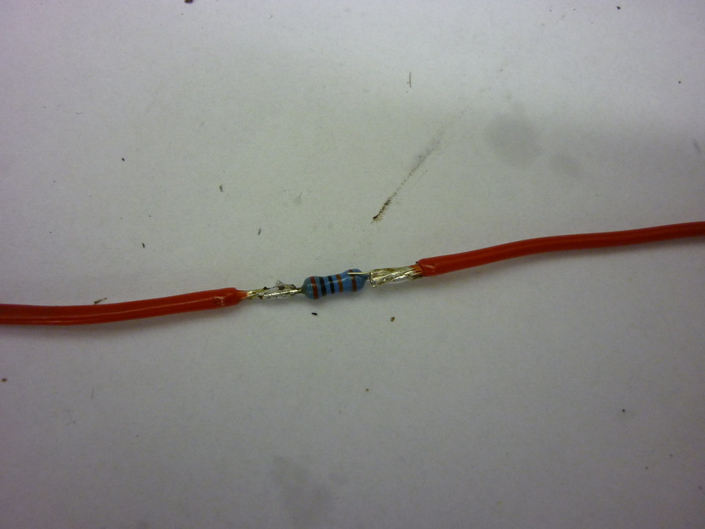 [/img]
[b]Job 2[/b]
Then you need a two postion switch (not sure if the std lumi is or not.)
I got mine from Maplin
[url] http://www.maplin.co.uk/Module.aspx?ModuleNo=2341 [/url]
Type A
The instructions that come with the driver say you need to switch the resistor 'in' to get 1/2 power and switch 'out' to run the full 670ma.
The solder connections when complete look like this
[img] 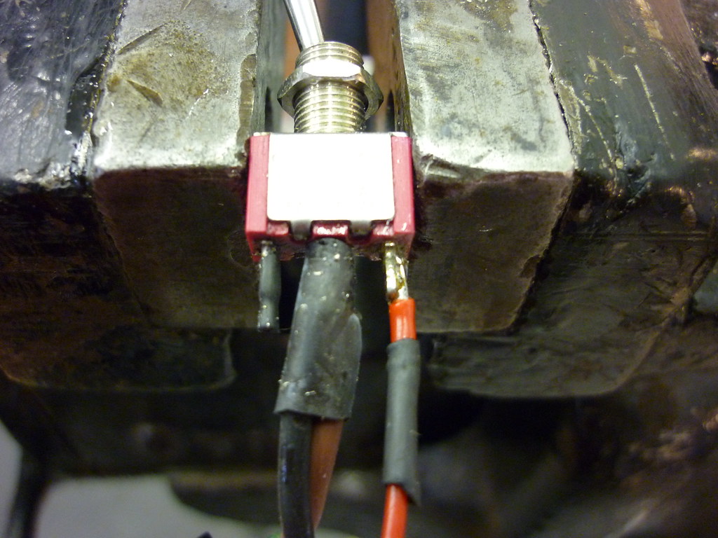 [/img]
The connections from the input socket to the switch and from the switch to the board (the black and brown ones)provide a non interupted circuit when the resistor is switched 'out' Ie as though the resistor is not there.
[b]Job3[/b]
then solder the resistor to 'A' on the board and .
[img] 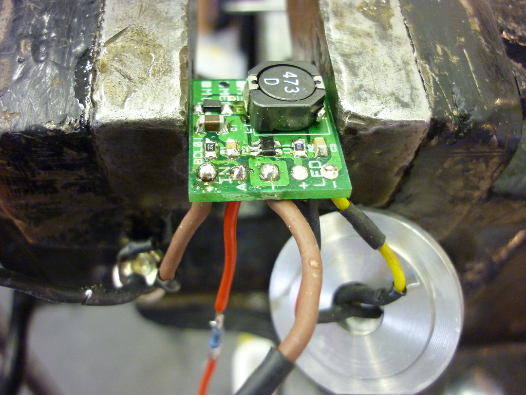 [/img]
The best way to ensure the whole thing fits in is to have the longer length of the driver 'across' the lumi can. This will give about 2-3mm more room.
The finished set-up (before trial installation) looks like this
[img] 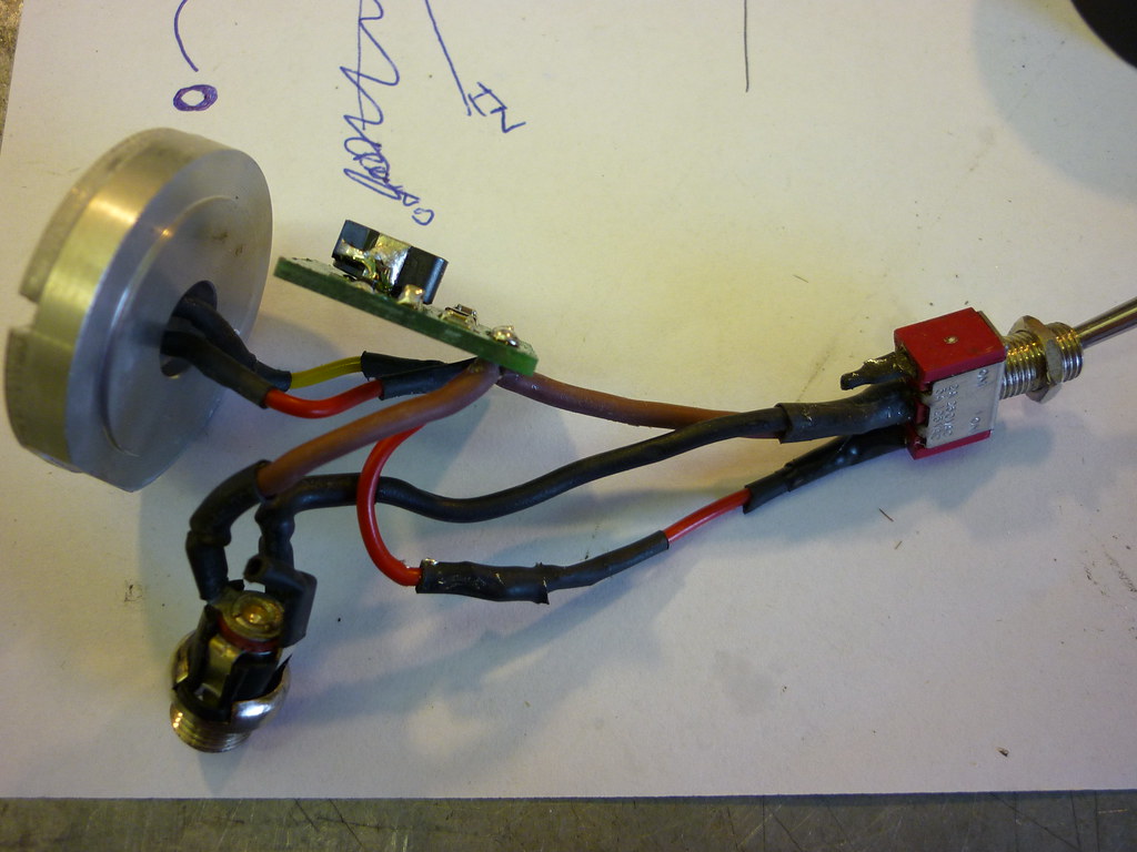 [/img]
As with the original conversion at the front of this post I find it much better to try the whole thing first and get all the wires 'formed' and shaped the commit to using heattransfer paste and do the final assembly.
Don't forget to insulate [b]EVERYTHING[/b] before powering up, this includes the resistor. This will stop anything shorting as it is quite a tight fit.
Hope this makes sense
cheers
Chuck
Hi Chuck,
I don't really get how you've wired it up - probably being dim, but I don't suppose you could perhaps scribble down a rough circuit diagram to explain pretty please? Have you configured it so that the two switch positions are on-low and on-high, so that you have to unplug the power lead to turn the light off? I have a driver but no instructions mentioning what the resistor should be connected to in order to lower the drive current. I was planning to add a second switch so that I have one for power on/off and one for current high/low. Cheers - really appreciate all the info.
Forgot to add, an alternative set-up for the resistor could be to glue it onto the switch body. That way it will be out of the way, and not 'stiffen' up the wire from the board to the switch. This method may help the wire bend easier.
Gray
.so that you have to unplug the power lead to turn the light off
yip you do have to unplug the power lead.
One option is that at Maplin they do on-off-on switch ie centre off and either way on.
The way I have wired it is switch one way for full power and switch the other way for 1/2 power.
The resistor is wired form A on the driver board to a 'outer' tab on the switch. It does not matter which outer tab you wire it to.
I'll try and do a wiring diagram and post later.
May take a day or so.
Im really keen on getting this upgrade done (as soon as the credit card turns up..shhh dont tell Mrs B)
Im getting a bit losts now with whats being ordered.
Chucky can I email you for a definative list or do you have spares of the kit that I can get direct from you?
mail me and we will see what we can sort out.
e mails in profile
Have you sent the order in yet Chucky? 🙂
yip order is in.
Just a point, a took up the registered mail. It was about £40 but considering the shipping was free due to the size of the order and there is about 16 of us (therefore works out £2.50ish each).I thought it was prudent to be able to track the stuff.
Plus thats nearly £500 on my credit card, so I would rather have a way of making sure it arrives for obvious reasons.
CRIPES thats a large order... 😀
I know
I've got a spreadsheet and everything 😆
I hope you lot don't change your minds or i'll end up with more lights than troutie.
BTW I could not find your bare XPG's anywhere nockmeister. they seem to be all mounted on PCB's. (probably not looking in the right place)
sorry but i ended up missing them off the order
can you send me a link and i'll try and sort it by seeing if they will add it on.
sorry
Dave
Nockmeister
sorry if you are a wizz at electronics then ignore this .
but do you realise the size of bare XPGs and how difficult they will be to solder too .my advise would be to get them on 10 mm square boards and if you do want them bare then remove from board
[IMG]  [/IMG]
my rainy sunday project was to remove 3 damaged leds and replace using a cobbled up reflow method I was dead nervous but had a successfull outcome
see vid
[url]
Wo I can't wait!
Hahahaha sorry trout, i meant the monetary amount of the order, 500quid on semiconductors is quite a lot! I work in discrete semiconductors so i know all about small packages 😉
er i'm going for pcb mounted LEDs as my soldering skills are non existant!! I have a buddy who wants a couple to play with in other projects...
Chucky - if you want some money now to cover the current cost, just let me know. We can sort out tax/duty etc later.
Cheers for sorting this out 😀
Your alright woody, i'll wait till everything arrives and we now the full cost.
Thanks for the offer.
Cheers for sorting this out
My pleasure
Chucky
Leds in the post this afternoon .
cheers trout
Mr Trout, did you find the LED's center themselves on the PCB with your DIY reflow . . . just thinking from an optical alignment POV . . .
Fd
Quick q. about heatsinking - does the heatsink actually need to touch the case, or is it sufficient to just draw heat away from the back of the pcb and into the case? I ask because they had some neat little self adhesive RAM heatsinks in Maplins which look like they'd be great, but they won't touch the case.
These - http://www.maplin.co.uk/Module.aspx?ModuleNo=98850
TIA
IMHO they should touch the case. that way the heat from the LED's transfer into the heatsink and then from that into the case.
I suppose the term heatsink is not actually correct, more of a heat transfer block.
Furgusd
yes if you look real close at about 4 mins 30 you see the top of the 3 leds settle in and twist around a little though I did try and get them in the right place before I started the heatgun .
it was a worry but the optic fitted perfectly after .
The heatsink needs to be in contact with the rear of the LED board and the case, you are trying to get heat away from the LED's and out of the case, not into the air in the case . . . given the cheap ebay heatsink, why do anything else . . .
Ref wiring diag, here's one for what is being discussed I believe . . . it's critical you don't screw up and mix up the connections - applying the wrong voltage to the wrong connection will fry the unit . . .
[img]  [/img]
Also for people doing this it's worthwhile considering some constructions tips . . . insulating the regulator is probably best done using some heatshrink tubing . . . you can get it on ebay, you're looking for something like 20mm diameter with a 2:1 shrink ratio . . . or 25mm with 3:1 . . . would be worth someone buying a metre or so and chopping it down for others, you only need say 30mm length . . . very neat and very strong compared to insulating tape for example which is really pretty useless . . . ideal for rattling around in the back of the can . . .
[img]  [/img]
Cheers all
there is also the option with a 3 pos switch to short direct the neg to A missing out the resistor as a soft off too
cheers fergusd
saves me doing one.
and a good tip about the heatsink. it is a much better solution than insulation tape.
I just didn't have the right size.
Yup,I didn't include the soft off option as the standard lumi switch is only 2 pos 😉 . . . bargain basement mode 😉
This guy sells heatshrink at semi decent prices for smallish quantities . . .
Fd
Thanks very much FergusD and Chucky. I received a couple of drivers from that nice chap on eBay yesterday, and the instructions (plus the circuit diagram above) make everything clear. I think I might run the 5W driver with a 100k resistor switchable in. That way I can run with a low mode of about 330mA and a high of 970mA. I figure that I'll mostly use this unit for road commuting. In traffic around town the low setting should be enough, but once I get out onto the country lanes with lots of airflow then I can opt for uber-bright. Might convert a second head unit later for offroad use. I also saw those RAM heat sinks and similar in Maplin. I'm wondering if it might be possible to mount something like that on the outside of the can, though obviously the heat sinks have flat bottoms, so would need some careful mounting to make sure that the heat flows nicely.
If you want to mount a heatsink on the outside of the can, have a look on eBay for RC car motor heatsinks, one of them - I think the 520 size - is an exact match for the lumicycle halogen case. It's a semi-cylindrical finned thing. I stuck mine on with heat transfer tape and it warms up fast, which suggests that it's working and dissipating heat.
It is all about heat transfer - there's no point in sticking a heat sink inside the can unless it can transfer the heat into the lamp body and simply having an interference fit between the LEDs and the lamp isn't good enough, you need some sort of heat transfer medium as well.
Sorry if that's all blindingly obvious, but if the heat has no way of getting to the outside world, then it will slowly bake your expensive LEDs. The heatsink is just increasing the effective surface area to lose heat from, but if it's simply heating the air inside the can, it's not going to be very effective.
Something like [url= http://cgi.ebay.co.uk/RC-540-Motor-Upgrade-Vented-Alloy-Heat-Sink-heatsink-B_W0QQitemZ200374783340QQcmdZViewItemQQptZUK_ToysGames_RadioControlled_JN?hash=item2ea7448d6c ]this[/url] btw
That looks ace! Might order one and give it a go. Cheers BWD.
No worries. My only concern would be landing on top of it on my chin, but it hasn't happened yet, touch wood 😕
I don't reckon the chances of that are very high. I'm pretty sure that I've never had any kind of face-to-bars impact. I reckon that'd be quite hard to do unless the bars snapped or something. Also, I'm hoping that my light will look a bit like a robotic baby hedgehog with the sun shining out of its a$$!
squeeky you ned to order thesehttp://www.cutter.com.au/proddetail.php?prod=cut781
Choose 3 way narrow for XPG
and
http://www.cutter.com.au/products.php?cat=Cree (plus) XPG
for some reason it won't put the plus sign in the link
choose R4 from the first pull down and cutter-XPGMR11T from the 2nd pull down.
Looking to order these, but slightly confused as to what I'm supposed to be ordering.
The cart shows the narrow optic which is correct, but I seem to have one cree xlamp xpg led at 5.95, the XPGWHT-L1-0000-00G51 R4 Bin and the Cutter-XPGMR11T.
Am I correct in thinking I will get a triple XPG mounted on a board?
Yep the Cutter-XPGMR11T is triple XPG mounted on a MR11 PCB
Er yeah the Cutter shopping cart is crap...I'm sure what u have ordered will be XPGx3 If u amend the XPG bin qty to 3, the total shoots up to 90 odd dollars..GULP!
Thanks for that, I thought I was being a bit dim there for a moment. 😳 I have ordered only one!
Woohoo! My LEDs and optics arrived from Oz today. I ordered XP-G optics, but they are listed on the invoice as XR-E ones, so I guess there are still no XP-G-specific ones. Ah well, I got a narrow and a medium so I'll just try both and see how they work.
let us know how the build goes gray
and piccies
I certainly will, though I'm waiting for a couple of bits to arrive from Maplin (three way switch, thermal tape, resistors) before I can make a start, and I'm off on holiday for a week from Tuesday, so it may not be until nearly Christmas by the time I get a chance.
Do you use anything to hold the feet of the optic to the LED PCB? If the wires etc. from behind are nice and springy and a tightish fit then I can imagine it might all sit happily in place of its own accord, but I was wondering about a little blob of silicone or something else (reversible, to enable optic swapping) on each foot to hold the LED board in where it's supposed to be relative to the optic.
I don't use anything. As the bezel on the lumi can hold it in place. but i think a couple of small blobs of silicon won't hurt.
I file the legs down a little so that they are not quite as deep as the LED PCB (you will notice they protude out the back of the PCB) . . . then use some rubber rienforced superglue to hold them in place on the PCB . . . you don't need to but it makes handling easier . . . it's always possible to remove it if required . . . only the smallest quantity is required . . .
I've been playing with the 970mA driver for a standard can conversion using XP-G triples . . .
The current regulator itself doesn't overheat at 970mA with an 11cell NiMh and running long term . . . good news as it's mentioned it may need heat sinking . . . but I've been struggling to get the 1/2 power mode working with the suggested resistor values . . . more experimentation needed . . .
Also waiting on some hedgehog heatsinks arriving from the US which I think will give a 1000 lumen helmet mount hog lamp . . . I think with the extra heatsink it will be fine in moving air . . .
Fd
All the bits have now arrived. Hope to get the light done sometime next week...
Just completed my Lumi can conversion:
[img]  [/img]
Comparison to my previous helmet light, a Hope HID (first picture)
[img]  [/img]
[img]  [/img]
(apologies for the shakey camera work)
I used the MR11 triple MCPCB with XPG-R4 LEDs from Cutter (I used R4s cos R5s were out of stock) and a Ledil XRE optic also from Cutter.
Note to Gray above, XPG optics are available but just not from Cutter yet. The Ledil site lists them and has links to datasheets etc. Problem is getting hold of them. I spoke to a couple of UK agents and they would have to order minimum quantities etc.
The LEDs are driven by a bFlex driver, again from Cutter, it's dearer than the ones listed on Ebay but much more versatile and programmable.
I also used the RC traction control hub as in the original post for the internal heatsink, which worked well.
I had also hit upon the RC motor heatsink idea and bought one from the States on Ebay, however BWDs suggestion was much neater so I used that instead (thanks BWD). I haven't yet had it running for more than 5-10 mins or so at full tilt (1000mA), however so far it doesn't seem to be getting red hot.
I can also recommend the heatshrink idea for sealing the driver board, much easier than insulation tape.
Other tips you might want to consider:
- to increase the amount of space inside the can I sourced an alternative toggle switch from Farnell, order code 957-5731. This is a momentary on and has a much smaller switch body. Also, I removed the plastic spacer so it sat flush with the inside of the can. You still need a spacer on the outside if you use the weather proof switch cover, I used a small length of Camelbac hose to provide a decent seal.
- This isn't necessary but I changed the power connection to a three pin Brad Harrison/Woodhead type as used on the original Hope, then made up a short adaptor lead from the Lumi connector to a three pin. This means I can use either the Lumi battery or the Hope one. This connector is also smaller than the original Lumi one helping to save space.
Thanks to all who have posted, this has been a very interesting (and so far successful) project. I'm currently waiting on a custom CNC housing to be made (should be done Monday) so I can fit all the components to make a x7 XPG R5 bar light (that's nearly 2500 lumens folks!)
Cheers
poisonspider