nice work ck. After I had already positioned everything I thought it would have been neat to fit the reflectors flush into the drilled plastic front and put the perspex on the front of the black plastic end cap, but maybe next time.
How can I test my soldering on the LEDs? I don't want to connect a 18650 directly, but an AA should be OK?
bigjim .... I thought about that too, but how do you seal the perspex on the front and make it look neat?
Don't think an AA will show any light, so unless you are putting a multimeter or milli-ammeter in the circuit, you won't be able to test anything.
How about troutie's method of direct drive? Whatever battery you're going to use plus a resistor. E.g. 9.6V battery - 6V (Vf *2) = 3.6V. Test current say ... approx 50mA, so 3.6V/0.05 = 72Ohm (68 ohm prefered value).
I cut the perspex to the same size and shape as the inside bit of the plastic panel, looks ok with the corners and edges sanded smooth. Would secure it by drilling for the screws and maybe a thin layer of clear sealant around the edge. With the depth of the perspex inside the black plastic end there are a few mm between the edge of the reflectors and the outside of the black plastic end piece, thought that might affect the spread of the beam a little. I think I'm thinking about it too much though!
I don't have resistors to hand and might as well wait for the driver and battery - was just looking for a quick check after the soldering. My soldering iron tip struggled to melt the solder on the star connections as the heat just got sucked away, so I used the edge of the thicker part of the iron to do it, just wanted to check the connection was good, it looks ok.
A tip that helps soldering the stars when on the heatsink
warm every thing up with a hair dryer or heat gun if you have one
I'm excited about the build now........
A quick battery question though: What's the current thinking on this? I'm thinking of 4 x 18650's in a holder. Any idea what the formulas to work out the output/runtime/brightness?
Keep up the good work
Webbo - people seem to be having some success with 2x 18650s, my drivers aren't ideal for this to be honest. I'm looking at options though.
Ideally, you want either three 18650s or 8x AAs as a minimum. To work out a rough idea of run-time, calculate the pack size in Watt-hours, so battery capacity (i.e. 2.2Ah) multiplied by the cell voltage multiplied by the number of cells. So 8x AAs at 2.4Ah would be 8 x 1.2 x 2.4 = 23Wh. The power drain is about 7W on full or about 3.5W on half power. Divide your Wh figure by 7 for hours run-time on full or by 3.5 for run time on half power, so our 23Wh would give just over 3 hours on full or about 6.5 hours on half power.
Finally got it sorted!! Finished my (2nd :oops:)rebuild last night and its amazing. Only managed a back-garden test, but its an incredible light output, though as some have mentioned it looks to be quite narrow. May get out tonight, but havent got the helmet mount sorted yet(using heavy duty velcro directly stuck on the bottom). Proper kid-with-new-toy feeling to this - magic. I will try and post some pics (if I can figure that one out) when I do.
Likely to be ordering from Digikey tomorrow - if anyone wants to put requests in for 18650 holders please do so quickly so I can judge numbers. I'll buy a few spares anyway for latecomers.
BCT,
As per my mail, can you stick me down for 1x4 cell holder please.
Let me know how much it is.
Cheers
Bobblehat.....It's ok, I know the high setting will have to be in the middle position, should have been more specific when writing my post, sorry :).
Mr Trout.....parcel arrived today, thank you very much. Even though I knew the dimensions of the parts, and I've seen the pictures in this thread and others, I didn't appreciate the size, they're tiny!. Very impressive output from something so small.
Anyone glued the stars onto the heatsink using AAA rather than screwing on? I know screws are the belts and braces approach, but I think the large surface area of the stars and the light weight will mean that they won't fall off, or am I going to be the guinea pig?
TSB yep done it loads of time with no problems at all .
AAA saving tip here mix it up on the heat sink where you are going to stick the stars and warm it up with the hair dryer helps it flow and set quicker .
I wonder if you could do something [url= http://forums.mtbr.com/showthread.php?t=498270 ]like this [/url]in one of these hammond boxes...
You mean like [url= http://forums.mtbr.com/showpost.php?p=6627564&postcount=157 ]this?[/url]
or
[url= http://forums.mtbr.com/showpost.php?p=6292902&postcount=164 ]this?[/url]
Hi all,
I've got my driver and kit from BCT, cheers BCT for being so prompt.
Now this is probably dead easy and obvious, but being a bit of an electronic numpty it's defeating me! I'm a little confused by the wiring of the plug, there are 6 pins but by by reckoning only three are needed. Can anybody explain/show the wiring?
Cheers in advance
webbo its a double thingy switch wotsit, I think you can ignore one row of the three pins
Just to reiterate what BCT said a couple of pages back - if you are sitting waiting for the driver kit for ages - check with BCT that he got notification of your paypal payment. I'd been sitting waiting patiently for 2 weeks before checking, and received it next day after sorting it out, so check if it seems wrong.
Bigjim, cheers for the swift response.
I see!
Webbo your kit will be in the mail today if I can hobble down the post office ( knelt on a nail yesterday and have a crocked knee now )
If I cant them wifey will post it tomorrow .
Trout - No worries if it's not till next week, I'm not going to have a chance to build it before next week anyway.
Hope your knee gets better soon.
CK ..... do you have to shave anything off the holders or are they 20mm across the flats? Have you tried any newer xp-g holders that are available now? I think they are round and 21.6mm.
Just in case, what's the original part # ... I know you posted it somewhere way, way back ... but it's so well buried 🙁
Thanks Webbo pain killers and alcohol are working
posted today along with a couple of others too .
daft question #1 : on black cat's cables, is the white marked wire the one that connects to the centre tip connection?
CK ..... do you have to shave anything off the holders or are they 20mm across the flats? Have you tried any newer xp-g holders that are available now? I think they are round and 21.6mm.Just in case, what's the original part # ... I know you posted it somewhere way, way back ... but it's so well buried
Not tried any XPG holders, these ones are from Carclo for their 20 mm optics(part number for black ones 10043). When I say these are a perfect fit to the case I mean they are a perfect fit, if you look closely you can just make out an impression of the end plate self tapping screw in the holder. There not quite a perfect fit for the Regina but a few dabs of silicone and you have a set of drop in reflectors.
I wonder if you could do something like this in one of these hammond boxes...
bigjim, hears mine
[IMG] 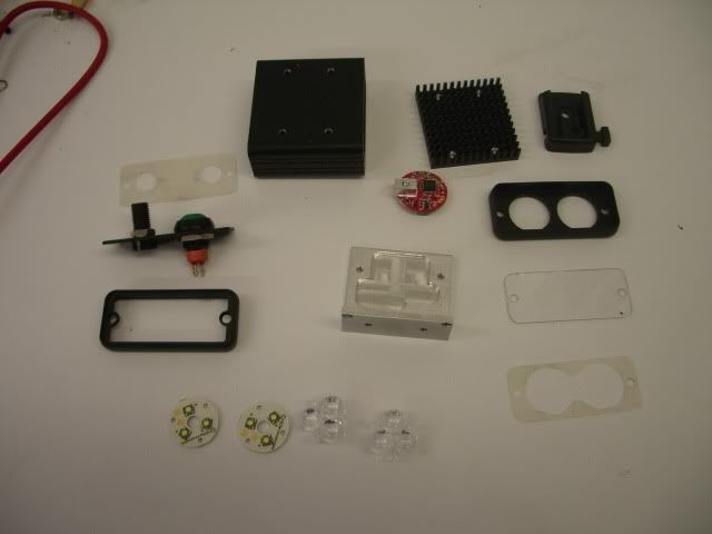 [/IMG]
[IMG] 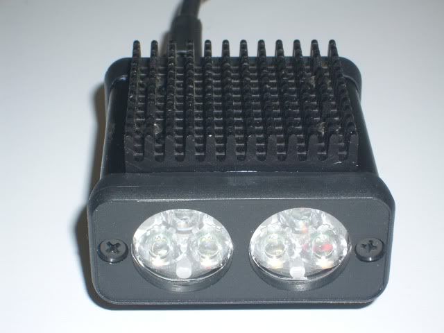 [/IMG]
[IMG] 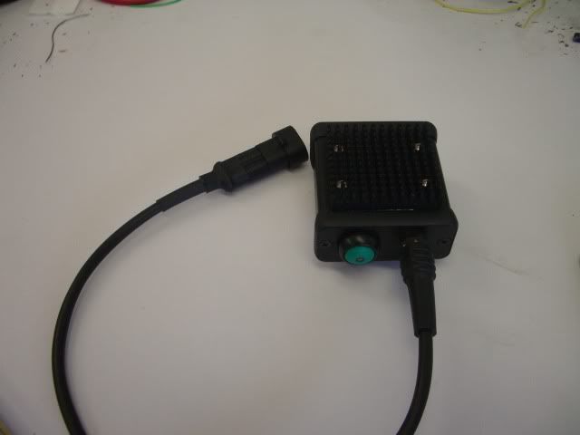 [/IMG]
Its very bright but a bit too floody and of course very power hungry. Aparently the XPE can give these optics a bit more throw. Trout, if you have a triple XPE lying around I wouldnt mind send some cash your way.
Thanks CK .... yes I can see the self tapper marks now you've pointed them out. Useful to know if the Reginas turn out to be a bit narrow for my "Dip" beam.
That's a nice set of parts for the double-triple! Must get hot!
Just completed a 1/2 power on the bench test on my two lights, both lights switched on with one common 8 cell Eneloop pack. Lights are built up with front fully sealed, backs screwed on but no silicone seal yet.
Some details:
Room temp 19C
No forced air flow
Start voltage of pack (off load) 11.1V
Resistors for 1/2 power chosen at 180Kohm approx 470MA through LEDs for each light.
Measured initial current draw from Battery pack (total for both lights) 620mA = 2 X 310mA.
Initial voltage on load dropped to 10.4V after 1 min and stayed steady for several minutes.
Case temp reached steady temp of 40C after 6mins and stayed there for the remainder of test - both lights pretty much identical.
Back panel always felt cooler than the case.
Test terminated when battery pack reached 7.2V under load (=0.9V per cell) at 2 hours 39 mins.
Total battery current load at termination of test = 810mA (405mA per light).
Pack bounced back to 9.4V off load.
I'm happy 😀
Love to hear any comments.
Question for all you experts 8) ... Now these light cases are only 38mm long of metal .... so the next test is to risk one at full power for an extended period...... at what case temp should I start to be worried for a no forced airflow test?
I was tempted to cut the case right to the edge of the alu L piece inside and make it a dinky little light, but didn't, wanted to see how hot it got first.
I think that was a wise decision bigjim!
From what Troutie said earlier ... I think 40C is no problem ... but my little cases will get very hot at full power on the bench. I'm hoping that they will be OK on the bike while moving, even on full.
I've just got a new 8 AA cell set of 7dayshop "good to go" LSD 2100mA batteries .... when I've given them a few cycles, I'll repeat the test above out of curiosity! Thinking aloud ... I've also got some Vapextech 2900 NiMHs that are well run in .... could be a nice comparison.
I'll leave the Sub-C 7.2V 3700mA NiMH pack out of the tests until I'm more sure of the light/drivers characteristics.
When the case starts to feel hotter than your tea when you drink it is as hot as I let owt get to .
if the light starts looking bluer then its nearly dead .
bearing in mind the leds will be 30 to 50 degrees hotter than the case assuming you have a good thermal path to the case
Full power and a walking speed airflow in the UK will keep it nice and cool on full on a case cut down to 50 mm long
Thanks Troutie .... gives me something to compare ... I'll make a brew (Yorkshire tea, of course!) and experiment! 😆
Built up my mk2 light today, it uses a slightly larger hammond case to allow me to fit 3 led's. The case is made in 2 parts so sealing will take a little more effort. I have also had a quick play on the lathe and knocked up an ali heatsink to try and keep the temps down a little.
[img]  [/img]
[img]  [/img]
[img]  [/img]
GaryS: Looks all good, whats the light like, any beam shots? What are you using as spacers between light and bracket?
no test yet, silicon is still setting. the spacer/heatsink is just a bit of round aluminium bar that i turned down on a lathe.
[img]  [/img]
What a beast! Very nicely done, GaryS! 1000 Lumens out the front?
Did you spray or anodise the heatsink?
What length is the case (front to back) and where did you get the fibre(?) washers?
The heatsink is sprayed with car paint, probably wont last long but it looks nice for the photos 🙂 The case is cut to 50mm, and the washers are punched out from a little piece of thin rubber sheet i found.
Interesting, I didn't know you could run more than two LEDs off the driver. Whats the handlebar mount garys?
I read in here somewhere that 3 leds would be ok assuming the input voltage is high enough. Hope i read it right! 😆
the mount is from lumicycle:
http://www.lumicycle.com/product/214/qr_lrg/qr-large-camlock-bracket.html
Cheers, looks a well made mount, I love how its still cheaper than the zip tie and plastic clip Exposure flog for a tenner for the joystick.
Mine works! Couldn't believe it. Put the battery into the holder like I was cutting a wire on an h-bomb, was expecting an explosion of lithium fire and hydrogen and arcs of electricity, but it works fine. Just need to build the 4x holder, stick it together and seal it and its done. Have restrained from comparing to the P7 lights yet...
Magic when it doesn't go "fizzzz" ain't it! Well done BJ
GaryS ... thanks for the info.
I got impatient and tried the "Good to go" batteries ...... pretty much same results as my Eneloops .... almost to the minute. That's good considering they have only been recharged once. So they may turn out to be worth the extra 100mA plus being nearly half the cost! I'll reserve full judgement until they have been sat around in a camera or something else for a while!
Right, lads, just got the new batch of PCBs and have been running some tests. Difficult decision coming now... I was hoping to keep the costs under control by changing from the Diodes ZXLD1360 to the AP8803. This is a cheaper version but has a few draw-backs. It has higher losses which means more heat dissipation. I was hoping to counter this by using a larger PCB and to a degree this has, the temperatures of new and old are about equal but still a bit higher than ideal.
I'm thinking that I'm going to have to stick with the more expensive chip for the 1A driver and use the cheaper one for lower power ones. I can do an 830mA driver at the lower cost and 670mA ones will be cheaper still as I've managed to do some other cost savings.
The new 1A / 830mA drivers are 24 x 20mm, the lower power ones are 21 x 19mm. All have better control options with shutdown and reduced power (approx. 40%) modes built in.
Just need to get components in bulk now and get some built up. I do still have a few of the old design if anyone wants to take them off my hands...
Hi Stephen ..... a bit confused ..... so what advantage has the new design over the old? Mainly thinking about the 970mA/1A versions, but a summary of the changes for the lower current versions could interest others.
I might only be speaking for myself but a few pence extra as costs rise is worth it if it preserves or improves the spec. I guess if they rise to a pound or two extra, that would make me look at other options ..... as it is I'm happy with the current designs, especially at the size they are at. Keeping the cost the same at the expense of the spec would not be high on my list.
some great looking lights on here, Im trying to upgrade another old Lumi can but cant get a response from Trout, anyone now the best way of getting hold of him apart from his website link. Im after XPGs and reflectors
Hi Ranger,
He's working in London this week so I guess he will have restricted tinternet access. He will either see your post on here and reply or email him direct to troutie @ blueyonder dot co dot uk. unless thats the address you have used.
I know he was having trouble over the last few weeks as not all emails where going directly to him but getting lost on his server.
Ive emailed him as well to let him know about you.
The old one ran a little bit hotter than was ideal, the new one has thicker copper and more area so will run cooler. I'd hoped it would be enough to allow me to use the cheaper chip as well, seems not.
The design is tidied up a bit, connections are further apart so less chance of shorts. You now don't need external resistors for dim mode while keeping the ability to have the soft-off mode.
Main thing is I needed to get some more PCBs made anyway so the changes seemed worthwhile. The smaller boards use a cheaper inductor as well as the cheaper chip.
I'd worked out prices for them all but have left the spread sheet at work. I believe the 1A version would be £6, 830mA £5.25 and 330/500/670mA versions maybe £4.50. Will have to post tomorrow.
As usual 10% discount available for direct payment for forum members but don't send any money yet, they aren't ready!
(900?)