Wow, Looks great CK, I need some more details on that battery pack is it double AA ? The colour makes it look like 18650's ?
Got my first one running tonight... Made it in 2 hours which is probably slow, but the finished article is fantastic...
The throw is phenomenal, really, really chuffed...
I'll try and get some trail shots tomorrow night..
Big thanks to Trout, BCT and smudge, there is nothing that can compare at double/triple the price point...!
I'm going to need more kits as all my mates are going to want one!!
Big thanks to Trout, BCT and smudge, there is nothing that can compare at double/triple the price point...!I'm going to need more kits as all my mates are going to want one!!
OOh er does this mean I can make a profit on the next lot . 😆 😉
Well done Clobber, really keen to see some beam shots. I'm planning on getting mine done over the weekend, inquisitive children permitting.
Expect my next lot of dumb questions soon 😉
Be very interested if someone can do a compare to a MS- Bastid
Well any othe lights too .
Ha and I got the 500 post
should have mine finished early next week,as I'll be away all weekend. then to compare against my ms bastid . ck hopefully I can get mine as neat as yours.
double post. smart phone my arse
Bct: hold a driver back and ill wait for full bct kit for him. (Still not yet received your package yet btw).
started mine. leds drilled as per ck and ali angle drilled.
then my drill battery ran out. grr...
still its the weekend - we'll have to see what i can get done.
lining up the holes for the ali angle fitting will be the hardest bit. need to get me some proper clampy things i think.
i`m guessing you more experienced chaps put everything together then solder?
trout and blackcat - will you post here when you know if you have more kits available or not. I'll try to be quicker off the mark this time. Sorry to pester you, just quite keen to build one of these bad bwoys!
Apart from AAA what else can be used to glue the driver and ali heatsink to the back plate - does it need to be something with thermal properties? i may be a tightarse, but im reluctant to spend another £5 for a tiny spot of glue which I will prob never use any more of ever again
I have used silicon in one light with out repercussions .
you can even make your own thermal glue with a good epoxy
and if you have a dremel grind some copper to dust but wear a mask .
of use a fine file and collect the dust .
you will be fine with araldite
not sure about flour and water glue though
Could I use cpu arctic silver I have left over instead of the ali glue(aaa) if I screw the leds down like ck has done, or does it need to be bonded?
Hows everyone else getting on, when will we see the next one?
Mines been for a road trip to work today, not really dark enough to tell yet but the beam is nice and tight. Will try and get some beam shots this weekend.
In answer to some of the questions, the Cateye spacers where brought from Wiggle many years ago, dont think they do them anymore.
The battery packs are home made, each takes 4 18650's and the packs spigot together to make on larger pack.
One tip that I found out too late is that if you cut the back from a Calco 20mm hex optic holder they are a perfect fit onto the reflectors. Assuming youve put the stars on 22mm centres it a great way of holding and centralising the reflectors.
Jazid Yep screws and the arctic silver paste is better than any Epoxy
Like I said at the beginning a smear of copper slip is as good as any
A guy has tested lots of different thermal pastes home mades and commercial and even water is good but does dry out though.
One tip that I found out too late is that if you cut the back from a Calco 20mm hex optic holder they are a perfect fit onto the reflectors. Assuming youve put the stars on 22mm centres it a great way of holding and centralising the reflectors.
Any chance of a link to these CK as I'm struggling to visualise it?!
As promised heres my next daft question;
Can you get self tapping 2, 3 & 4mm screws suitable for this build? Any
helpful links? I've tried my local model shop but they only had 2mm x 8mm in stock and werent very forthcoming about gettin others in.
Have a look in any old knackerd electrical stuff usually find an assortment of self tappers used in them .
Like old computer screws etc?
BCT can I get a driver off you please email should be in profile.
Any chance of a link to these CK as I'm struggling to visualise it?!
Have a look at the original build hear http://forums.mtbr.com/showthread.php?t=407160
You can see the optics in the hex holders, these holder are a perfect fit in both height and width for the case.
If you cut the back away from the holder your left with this.
[IMG] 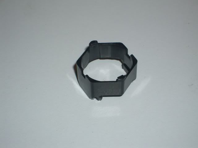 [/IMG]
The holder will clip over the end of the reflector leaving two small plastic tabs slighly proud, you need to take acount of the extra length when fixing the position on the angle plate.
Ck, fatastic work and thanks for the 2008 easy diy link.
Thanks Trout.
Bct, your processed cheese slice packaging has arrived, cheers.
Could people point me to what silicon product they are using?(I may have missed it in the last 500 posts!)
Also does anyone know if pc case screws are typically self tapping?
[b]CK[/b] What are you using to make your silicone gaskets from and is normal household bath sealing silicone ok to use for around the switches etc or does it have to be a specific type?
What size holes did you drill in the end plate for the switch and power lead?
[b]Jazid[/b] Not sure if they are but will try using them later once I've done my drilling. Not had a lot of luck sourcing screws, got some 2mm from local RC shop however there 10mm long and heads cover the gold coloured contacts on the LED star. Not sure if this is a bad thing or not? A trip to Maplins is in order which I'm sure will be lovely 😕
As far as the holes to be drilled are concerned does the M number, i.e. M2 mean that it needs to be done with a 2mm drill bit etc? Sorry if this is obvious to all you engineering types out there, I am but a humble numpty 😀
Any silicon really but not the acid cureing type
or if you do use the ones that smell of vinigar then make sure the cure fully before sealing up the light .
http://www.maplin.co.uk/Module.aspx?ModuleNo=46001
this ones OK for sealing and glueing.
Lots of self tappers in a PC case
Stayhigh
M2 needs a 2 mm hole unless you are tapping it and then it needs a 1.6 mm hole .
The aluminium is very soft so even wood screws will cut their own thread .
just drill a slightly smaller hole than the screw
Dammit I was only at Maplins earlier. I got some screws that are m2.5 x12mm and also come with nuts so if cant get them to thread can always do them up with them. Looks like I'll be heading back there tomorrow 🙄
I went into Halfords to get some [url= http://www.commaoil.com/productsguide/view/6/220/CE20G ]Copper Ease[/url] and while there noticed they had a pillar drill. I jokingly asked the girl serving me if I could use it and she went and got somebody else who drilled the holes in ali angle heatsink for me. Bonus 😀
The downside to all this is they didnt have a 2.5mm bit so the holes are 2mm but from what you say trout that should be about right? I'll head back there tomorrow and see if they'll do the other one for me too as it saves me going through the kitchen table lol.
At this rate I maybe able to get dangerous with a soldering iron later this evening.
Hows everyone else getting on?
ps: Does it matter if the screw heads cover part of the gold coloured contacts on the LED star?
same as bigjim here, trout/balckcat, if anymore kits were to come up i'd certainly be interested.
Well I'm slowly working my way through the screwing through the angle heatsink and have found that putting a bit of chain lube in the hole helps the process nicely 😉
Ok I've got my holes done and threaded in the angle heatsink which is cool. I was about to whack on the LED stars and then remembered some mention of "insulating material under the screws to make sure they dont short on the solder pads"
What can I use for this, could I make an inner tube washer or would that be not quite upto the job?
Nearly done just have to solder the wires to the driver should be done tomorrow. So if you hear a big bang and see a mushroom cloud over southport area tomorrow that will be be connecting the battery. 😯
Lipseal; Well done fella, fingers crossed for battery connection tomorrow. BTW, have you used any washers or the like where youu have screwed the starboard onto the heatsink? Thats where I'm currently stumped?
Stayhigh have a look at the CK picture on page 11 and you will see he has used counter sunk screw heads, they just hold the LEDs without going over the board too much. Look for 3mm fiber washers on eBay you can get some for a few quid, failing that some mentioned making washers from oven read meal packs as they can take some heat also maplin do shake proof 3mm screws that have o rings fitted. HTH
Hey trout and the LED collective...
Re: troutie old little one 😯
Not much LED construction coming out of the LT workshop atm, sorry guys. I'm currently up against it work wise atm.
That said, I'm amassing parts: power socket gonna look tidy; thinking of adding a visor to the unit to increase surface area with heat loss in mind...have pivot mounting in mind..might separate two small&thin Ali plates between mount and unit for further heat sinking.
Any news on CK's mounting source??
I've a few fibre type washers with my motherboard screws, used for putting under the screw heads. Anyone know they are likely to stand upto heat?
Also how can you tell if screws are self tappers?
Thanks for the replies and sorry for the stupid questions.
Jazid wood screws have a slightly more corse thread than a self tapper plus they are made of a harder material, as for the washer they will be ok.
So are you suggesting wood screws as a better alternative?
Forgive me if people have already posted this, but I found this for a battery lead connector idea on my ebay watch list.
Magicshine 900 Lumen Bike Light 1 Meter extension
http://cgi.ebay.co.uk/ws/eBayISAPI.dll?ViewItem&item=180566313468
Trouts right about the silicone, you need a nutral cure. If you have an acid evolving cure you will corrode you solder joints and if you assemble before full cure you will have a corrosive fog inside your light.
My LED's are fitted with pan head M2 screws which are way to small for the slottted holes in the stars. I've adjusted the centres of these to 18mm so the screws positivly locate the stars and then fitted small fibre washers under each one. I to couldnt source fibre washers so had to make my own from some this insulating sheet.
I think you will struggle to source Cateye base plates anywhere, mine were brought several years ago and they just dont seem to be available anymore.
Tapping sizes for metric screws will be the size minus the pitch, so M2 is 0.4mm pitch so tapping size will be 1.6 mm.
No not wood screws jazid as they are soft and could snap when being screw into the hole.
Morning All
The screws that I have are'nt countersunk however they dont cover the gold contacts either so would I still need to use a washer?
[IMG]  [/IMG]
The star does slightly overhang the angle though so will this need to be filed down in case it shorts anything out?
And just to check I got this right; one star has a + at the top and the other the - when placed on the angle?
Thanks all, I think I'm getting there 🙂
Sorry to disagree on the wood screws thing. they are hardened nowadays to withstand the torque from the
lacy screwdrivers .
and if you drill your holes just a little smaller than the thread dia. it will tap into the soft ally OK
Hi Stayhigh .. have a read of Lipseal's comment on page 12, around the middle, regarding insulating the screws from the star ... it surprised me! If Lipseal's experience is typical ...it's almost like you might be trusting things to luck ... not a good idea!
Stayhigh, man youve got good finger nails. Dont forget that the angle is 19mm and the case is 20 mm, I just set my stars so they are flush with the base.
In theory if your away from the solder pads you should be good to go, you could check with a meter. I would go with insulating washer just to be on the safe side.
All done not explosions or puffs of smoke just need to glue the driver to the rear cover job done. I'll get the pics up tonight and I might put a bigger resistor in as there doesn't seem to be much difference between high and low(tested in garage) but for now it's ok.
Was just covering my back trout 😉
Betcha can't wait for it to get dark now. 🙂
😆
Been wonderimg about the possibility of a 6 led fitting in the 120 mm long case .
[IMG]  [/IMG]
Dont know whether to give it a go or sell 3 more kits when the leds arrive