What is AAA, and what else could be used to glue driver to ali and ali to backplate?
the thremal epoxy paste linked earlier in the thread for glueing ali bits
trout: box of leds and stuff arrved safe and sound.
parts gathering accomplished now all i need to do is acutally build it. i`m moderatly nervous and excited in equal measure. i'm fairly convinced i'll blow something up so i hope there are some spares...
i like the idea of drilling the leds but... *gulp*
Stayhigh, i'll swap your seperate for my one piece if you want?
RWS: have emailed you about swapping ends 😯
stayhigh, the swap is on!
Be careful of the black covering on the LED's as Ive scratched mine and earthed it 😳 . Just test your connections with a multimetre first.
Sounds ominous! Lipseal .... could you add a little more explanation .. I'm not quite sure what the scratch to the black covering of the leds has done? Thanks bobbl@
Well bh I can now see the copper that's under the black covering, and was just checking the circuit found the middle screw had earthed one of the LEDs. Removed screw and could see a small scratch will have to find fiber washer of some sorts.
Can anyone recommend a grippy 5.5/2.5mm power plug - my maplin one has a smooth inner barrel and doesn't 'hold' the socket too well.
(The 2.1mm ones were a different design - but I already put a 2.5mm socket on the light.)
has it got the split centre pin cos you can open it a tad carfully and it will grip a bit better
For insulating washers I was going to cut some from leftover oven-ready meal containers. Should be able to take the heat OK.
Good idea v8
Got it LS ... Thanks. That's one less mistake for me to make. I love these forums!
As LS says ... Good idea V8!
'Done that' - thanks troutie - I thought about a £6 IP68 locking one - then decided that 'loose ones' crash better(?)
If anyone didn't manage to get the DIY pack I've
(a) Tidied my desk and found another switch lurking
and
(b) bought a few double-pole switches from Rapid
I now can supply another 4 packs if anyone needs them.
(Jazid, you pack with extra switch is on the way!)
Is the AAA electrically conductive or insulative? (This usually depends if it is metal or ceramic-loaded) The two small holes on the driver can be electrically connected together but not to anything else.
Certainly worth using insulating washers when screwing the LEDs down to avoid any potential problems. Temperature shouldn't be a major issue - if you are getting over about 80C at that point you are frying the LED die anyway...
Thanks BCT.
I have just realised that all the PC case & motherboard screws I have lying around might well do. Not sure what threads are on these those and what sort of tap they will suit.
AAA = Arctic Alumina Adhesive
http://www.arcticsilver.com/arctic_alumina_thermal_adhesive.htm
non-conductive.
@blackcat - is that four packs of your part, as in driver, switch etc, or the full shebang? Also, ot, but do you make drivers for other lights? I've been trying to find a UK source of P7 drivers (and 18650 holders) to mod a couple of dx torches I have but it seems a dead loss. Very wary of ordering anything from the states after getting thoroughly done over on import tax on a t shirt recently.
Bigjim - Yes, just my parts, not including LEDs / reflectors etc.
The P7 is a right pain to make a driver for. Cree got it right with the MCE by making the 4 dies available independently rather than Seoul putting them in parallel. I am looking in to a two-channel 1.5A driver which could be paralleled and set to give 2.8A but that is only in the planning stages at the moment. It will also be bigger than my existing ones, probably 30x30.
Digikey do 18650 holders but you need to spend £50 to get free delivery. They pay the duties, you just have to pay VAT to the nice chap from UPS, no extra fees.
Bigjim - I have just bought some 18650 holders from this company http://www.luminousdiy.com/Light%20Kits%20and%20Parts.htm you have to build them yourself though.
Blackcat, i'll take another set please....address for payment as before?
runswithscissors - yup, address as before but due to the components price rises I'm afraid I'll have to put the pack up to £9 including P&P.
Only one left now!
Ok will send payment tonight BCT.
bct, you've got mail..
Bct, Can I put a hold on the other one?
Trout do you have another set to make another light please (I've a friend who put in a request for a light kit if available)?
All kits now reserved! Wish I'd know how fast they would go, I could have added a few more bits to the Rapid order I did yesterday...
Damn too late again! <cries>
I do have some more leds coming in hopefully next week
and have a few Optics in stock .
so will be able to supply a few more kits.
anyone got one working yet
Trout, put me down for one then pls.
trout, I would take a kit if black cat had the driver etc available, or I might take one anyway when I can do some homework and check what I can do regarding sourcing the bits elsewhere.
Has anyone managed to finish one yet 8)
cant wait to see the pics of your completed lights
Actually trout if you do get spare kits together I will take one and figure out drivers etc after - its a good chance to get the leds and reflectors. thanks!
You can't rush a good job! 😉
Troutie ...I'm still interested in buying 4 * 20mm xp-g's off you from the next batch! And if you still want them ... I have the 3 * 8mm xp-g's that I dare not solder!
Has anyone come up with a good solution for helmet mounting? I'm guessing noone has been able to source the Cateye spacer that would make the job a lot easier. I've bodged something out of a plastic bottle opener to interface with a HOPE helmet mount I've got. I'm not convinced it'll be secure enough tho so don't want to drill the case if anyone has a better option. Trout, how did you mount yours to your helmet as per the picture on page 4 or 5? Is it some kind of velcro like material stuck to the bottom of the head unit?
i'll take another kit off you please Troutie.
(money sent BCT)
Light progress.
Switch and cable entry fitted to alloy end plate. Heatsink plate cut to fit and holes drilled to match solder pads.
[IMG] 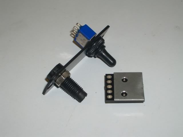 [/IMG]
Driver bonded and wired in place.
[IMG] 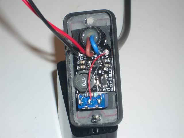 [/IMG]
Led's wired in.
[IMG] 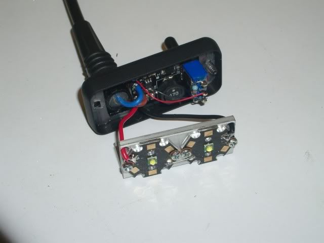 [/IMG]
Reflectors bonded in place with silicone.
[IMG] 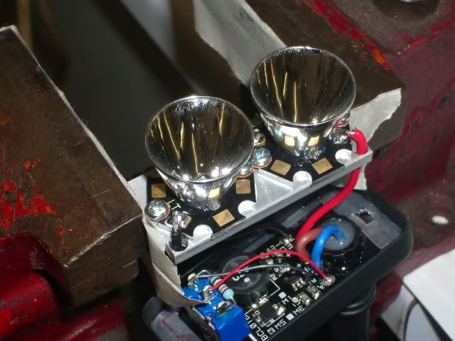 [/IMG]
Plastic front bezel and perspex cut and silicone gasket made
[IMG] 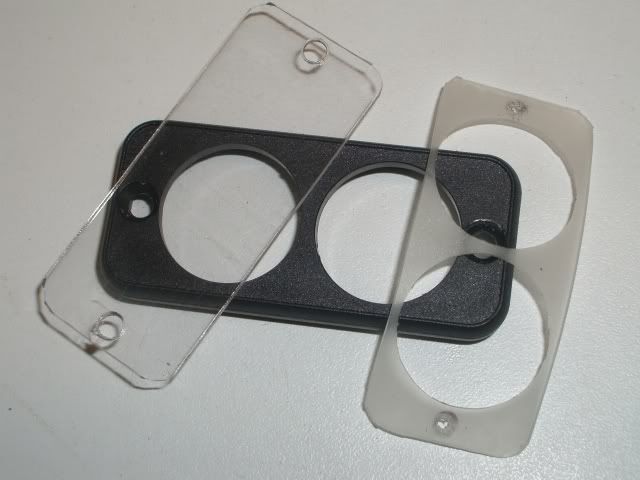 [/IMG]
Done.
[IMG] 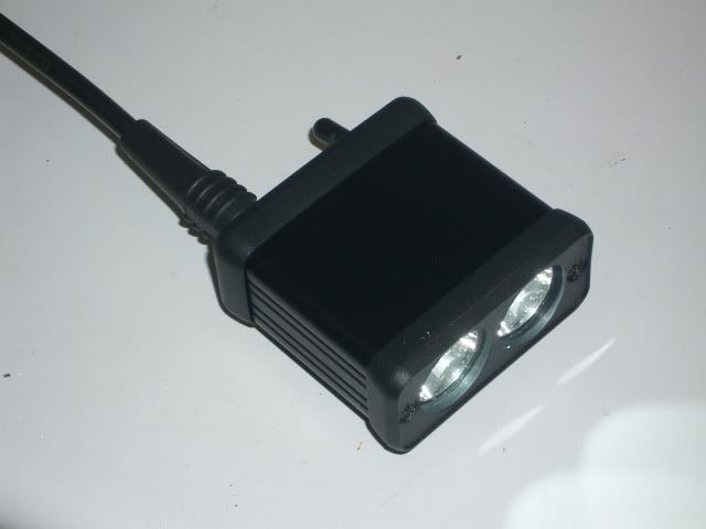 [/IMG]
[IMG] 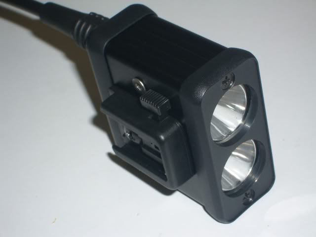 [/IMG]
This is my battery solution.
[IMG] 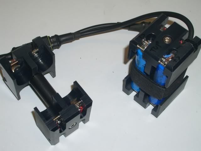 [/IMG]
Wow CK thats really nice, hopefully mine will come out nearly as well. What did you use to drill through the ali end plate. I know it may seem like a painfully obvious question but I'm not that upto speed on these things and have a limited set of tools at my disposal.
Lazymike yep heavy duty Velcro got it from B&Q about 5 years ago
put the loop on my helmet and now afraid to try and remove it .
but holds the CK light on perfectly in fact it hard to take it off .
Bob yep should be no problem .
Scissors whats BCT mean 😳
I think the whole world is holding its breath waiting for a finished light .
Edit
And breath 😯
Nice one CK very tidy
Nice looking unit CK,
May I ask how you bonded the heatsink to the driver board; in the pic I can make out what looks like solder 'cusps' to the centre of the holes you've drilled. Do you/have you then filled these holes with solder to connect those 'cusps/blimps/remenants' to the heat sink plate?
Thanks.
LT
Hail CK ... glad to see you're still "at it"!
What's an easy source of the sheet you used to make the gaskets?
Your going to hate me for this, I have a milling machine so its dead easy for me to drill holes. All the holes in the alloy are drilled with simple twist drills, the holes in the front plastic bezel were drilled with a 20mm slot drill.
The heat sink is bonded to the driver and back plate with Artic Alumina. Despite AA being non conductive the holes are just an insurance policy to make sure I dont bond to copper on the PCB.
The silicone sheet material was a free sample that I scrounged from an o ring manufacturer some years ago, if you dont ask, you dont get.
I should say that I had rather a large advantage as I already had a full set of drawings that only needed a few mods to adjust for the length of the reflectors, the rest was exactly the same as an Easy DIY build.
That's one sexy looking light CK..er of course it's not complete without any beam shots 😛
Where did u source the CatEye mount??
CK - looks stunning, you could sell those! The two holes you have 'avoided' are electrically connected on the circuit board so no problem if you just connect them to each other with the heatsink but it could be a problem if you connect them to anything else.
Jazid - sorry, all kits went before you got in I'm afraid! Next time I order from Rapid I'll add some more switches and connectors as I think I will start selling the complete kit as an item. I've got plenty of drivers left if you can source your own power connectors and switch.
CK, Excellent job done mate 8) I can see you being a tad busy once a few on here see that 😉
Have you christened it yet?