- This topic has 1,254 replies, 94 voices, and was last updated 12 years ago by stevemorg2.
-
DIy 700 lumen batteries inside light
-
defaultslipperFree MemberPosted 13 years ago
Well I finished all the electrical bits at the weekend, just in time for a quick ride on the Sunday evening. It’s a great little light, thanks to troutie and BCT for taking the time to put the kits together and letting us mortal lightbuilders have a go at building a cracking little light for not much money!
Some obligatory build pics:
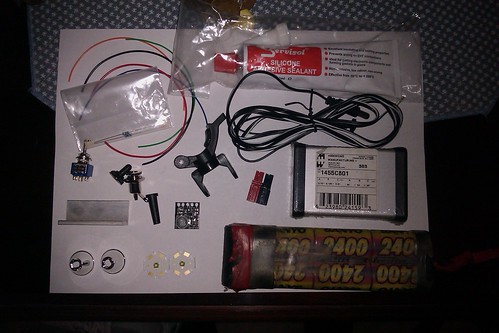
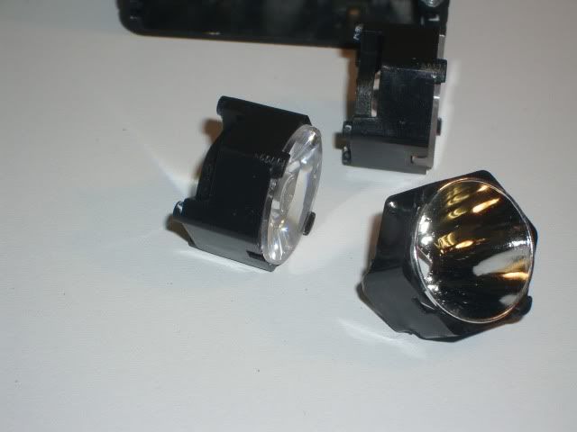
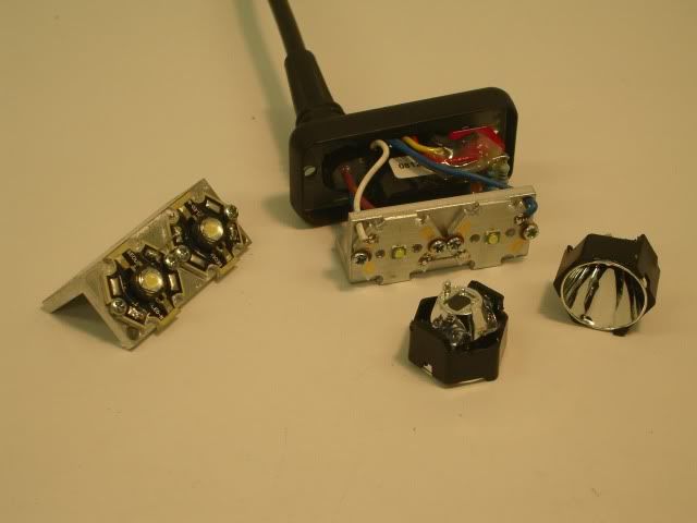
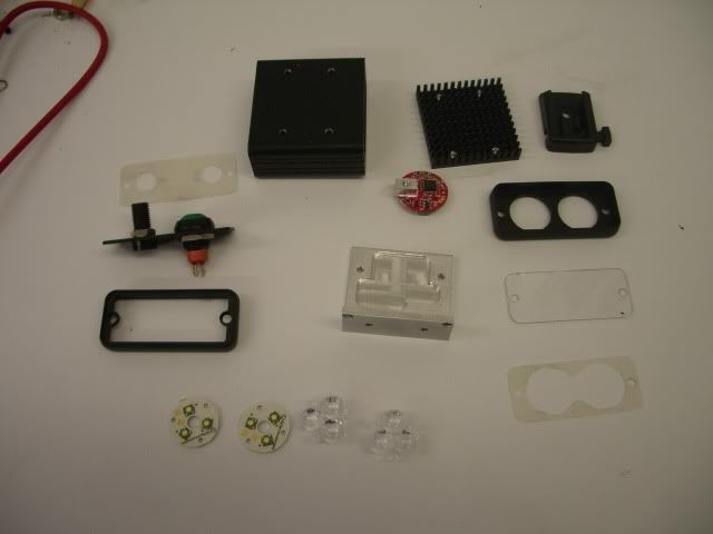
The full kit I used (minus a few Tamiya electrical connections and the 5Amp cable I used). Silicone was the Maplin stuff, a bit expensive but saved me searching around elsewhere for it. Didn’t use any of the AAA thermal stuff, just copper slip.
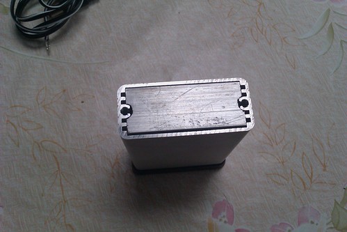
I decided to cut down the L-shaped heatsink from troutie to make it a tight fit to reduce the need for the extra screws on the bottom, adn therefore hopefully improve weather-proofness. Had to file off a little of the metal tabs inside the hammond box and a little more off the side of the heatsink to allow the wires going to the LED some space.
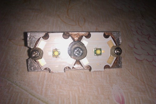
Had the same problems as mentioned on this page in that the holes for the LED screws were slightly off so had to file a mm off the LED stars, but no hassle. Used some offcuts from RC car spares i had lying around for the little screws and then cut a bit of plastic for the larger centre screw- not exactly pretty but does the job perfectly for me, and the uglyness is hidden behind the reflectors!
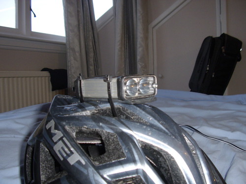
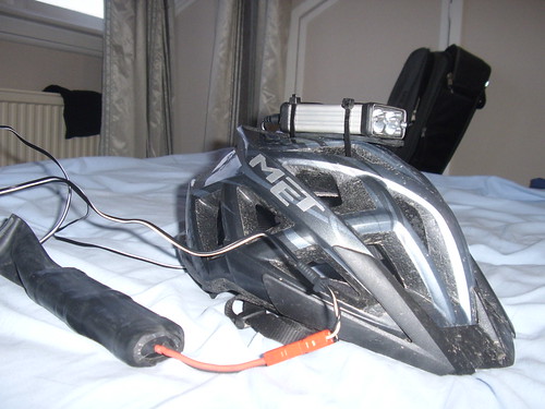
Going to use it as a headtorch to start with, so just a simple inner tube between the helmet and box so that I don’t melt my helmet, and then 2 zip ties around the top. Feels pretty solid, but obviously not good if you need to take it on and off, or to find the right position to start with. Using it this way also means I don’t need to cut the box down so it is more stable on the helmet. Another plus is that the heatsink is not attached to anything currently so there is a bit of space inside the box for it to dissipate the heat.
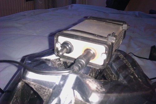
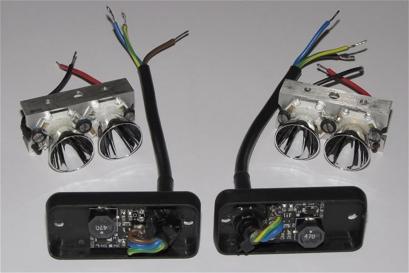
The backplate. I didn’t take a picture of the inside of this but because i got one of the larger switches off BCT, I didn’t think there would be enough space to attach the heatsink, switch and power plug to the same plate.
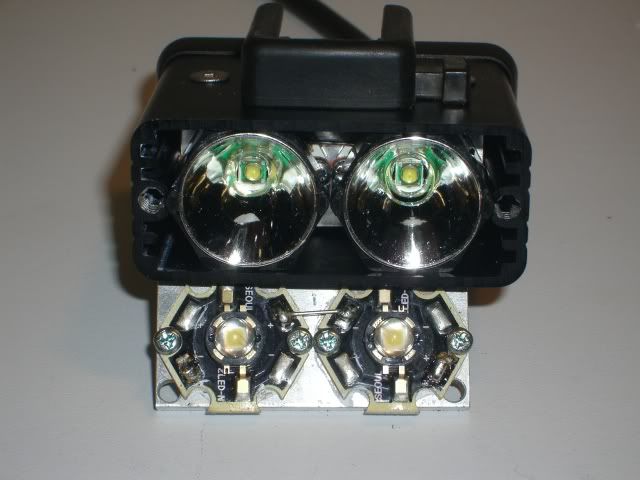
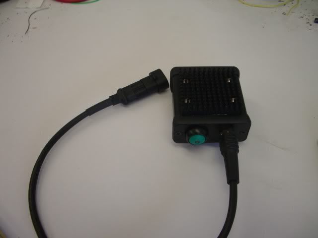
The full build as it stands. I am testing all my old batteries to see if they will provide a long enough run time. Inside the makeshift inner tube bag here is a 6 cell 2000mA Ni-Cd battery which gives about 8.4V hot off the charger, although it is only rated at 7.2V, so I am expecting it to cut off before it is anywhere near fully discharged. Fortunately I have a 7 cell Ni-Cd which gives 8.4V (9.6V off charger), with an expected runtime of 2 1/2 hours on high I think, which is plenty of time.
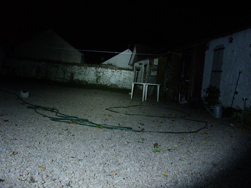
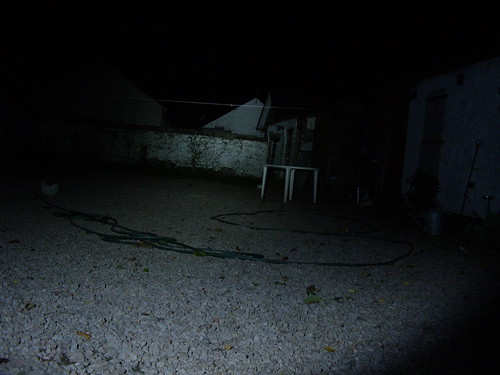
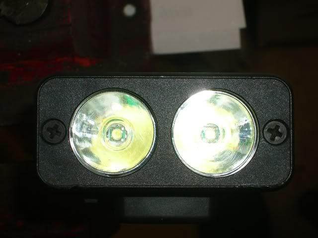
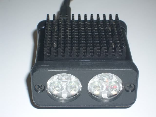
And finally some beamshots. Only taken with a point and shoot in manual mode so isn’t exact but gives a fairly good visualisation of the beam. both taken in the dark with no other background light/ moonlight. Because I used a garden chair they are also not straight, but you get the idea!:
High setting
Low setting (using the larger resistor)
It gives a pretty good wide beam, and a concentrated spot without being too bright, and definitely enough light to be used on its own. Unfortunately when i went to test it on Sunday it was raining- I havn’t finished sealing it up yet so tried to keep it covered. But when it was used in the rain it worked perfectly, with no issues. Once I have finished off the last few little things it looks to be a great cheap, bright, weatherproof light.
Thanks to everyone on here who has contributed their knowledge, time and patience. And for those who havn’t finished it, or started it, get on with it. It’s good fun and feels great using a light you have put together yourself, and highly addictive- I have already begun plans for another project!!!bobblehatFree MemberPosted 13 years agoCan’t add my name to the finished list yet. Slow progress …. that’s me really to a T. 😳
Not fully built but tested and working, checked for short circuits, joining these two sections together temporarily and powered them up with a bench supply. Heat not too bad even on the bench at 970mA.
Next step …. put them into the cases with some cpu heat sink paste and some silicone for the front and rear and screw the lot up (if you get my meaning …. nervous ha! ha!).
I have to admire the guys like Troutie and CK and lipseal that can do this all in one night (or nearly!) 😯
Just got to get the mounting and the remote switches sorted and I’ll have a high/dip/high+dip beam bike light system!
Dynamo light is progressing well in the meanwhile.
bobblehatFree MemberPosted 13 years ago😛 … gotta get those extra lumens out … if only for a short while! 😆
Edit: … I intend to ride in a circle of approx 30m radius … .that’s the length of my longest mains extension lead!
 puntopeteFree MemberPosted 13 years ago
lol
postman left me a note today so can’t pick up the package till tomorrow 🙁
webboFree MemberPosted 13 years agoThis thread is great, there’s so much info on it! The finished lights look awesome.
Trout: Do you have any leds/reflectors left. You mentioned you might on the last page.
Cheers in advance
bigjimFull MemberPosted 13 years agoHey bobblehat, have you got a pic of the back of your back panels if you did your cut out plastic for heatsink thing?
puntopeteFree MemberPosted 13 years agoTroutie, BCT…..
kits received, many thanks for your efforts.
now to sort a case, hammond or do i mill something out of the scrap box at work….. hmmmm
troutFree MemberPosted 13 years agoWebbo
Yep got plenty of leds and reflectors if you want some .
By my reckoning there are between 50 and 60 of these lights being constructed with the amount of leds I have sent out .
Cool 8)
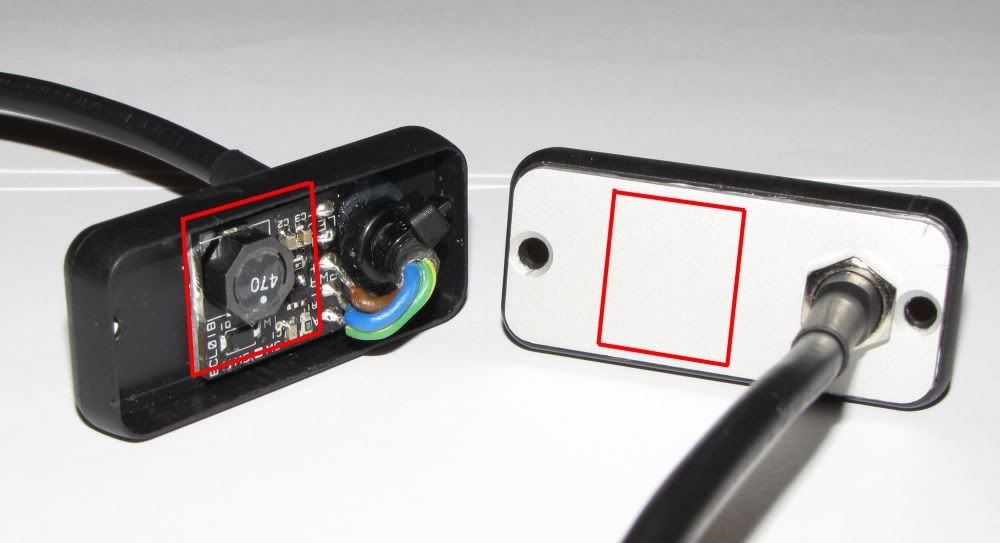
bobblehatFree MemberPosted 13 years agoNot much to show bigjim … I took no photo of the rectangular hole in the solid plastic end cap. Here’s the assembled back. I’ve indicated the area of plastic cut out.
If I’d have had more skeleton bezels like I used on the front, I’d have no need to cut the rectangle out the end cap to AAA the ali piece Troutie supplied to the ali back plate. As you can see, it’s a neat arrangement. The ali back plate (seen on the right) is AAA’d to the black plastic end cap.
As I said before, if anyone is going to do this, I suggest cuting Trouties piece of ali down a bit so that its about 13mm – 15mm from top to bottom …. it means the hole you cut out is just 13mm+ to 15mm+ and leaves a nice little plastic edge top and bottom to put some AAA around … keeping things watertight.
webboFree MemberPosted 13 years agoTrout,
Sweet, nice one chap. Would you prefer direct mail about the purchase rather than on here? You must be snowed under with requests for your knowledge, what with being a resident light expert on here and the MTBR forum and the number of DIY lights popping up. Thinking of that…..is there a danger we’ll contribute to light pollution? (The last comment was only joking, this thread is argument free so far!)
By the way what external batteries are people using? Is a mail to smudge required?
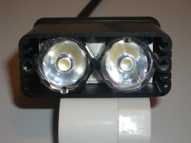
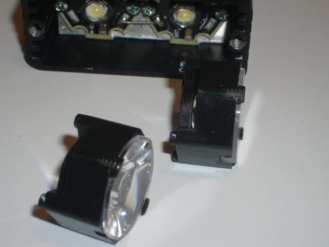
citizenkaneFree MemberPosted 13 years agoI purchased a few more leds and reflectors from Trout to upgrade some old lights, same as before just a slightly different way of fixing the reflectors by glueing them into holders instead of the stars. I’ll let the pictures tell the story.
bigjimFull MemberPosted 13 years agonice work ck. After I had already positioned everything I thought it would have been neat to fit the reflectors flush into the drilled plastic front and put the perspex on the front of the black plastic end cap, but maybe next time.
How can I test my soldering on the LEDs? I don’t want to connect a 18650 directly, but an AA should be OK?
bobblehatFree MemberPosted 13 years agobigjim …. I thought about that too, but how do you seal the perspex on the front and make it look neat?
Don’t think an AA will show any light, so unless you are putting a multimeter or milli-ammeter in the circuit, you won’t be able to test anything.
How about troutie’s method of direct drive? Whatever battery you’re going to use plus a resistor. E.g. 9.6V battery – 6V (Vf *2) = 3.6V. Test current say … approx 50mA, so 3.6V/0.05 = 72Ohm (68 ohm prefered value).
bigjimFull MemberPosted 13 years agoI cut the perspex to the same size and shape as the inside bit of the plastic panel, looks ok with the corners and edges sanded smooth. Would secure it by drilling for the screws and maybe a thin layer of clear sealant around the edge. With the depth of the perspex inside the black plastic end there are a few mm between the edge of the reflectors and the outside of the black plastic end piece, thought that might affect the spread of the beam a little. I think I’m thinking about it too much though!
I don’t have resistors to hand and might as well wait for the driver and battery – was just looking for a quick check after the soldering. My soldering iron tip struggled to melt the solder on the star connections as the heat just got sucked away, so I used the edge of the thicker part of the iron to do it, just wanted to check the connection was good, it looks ok.
troutFree MemberPosted 13 years agoA tip that helps soldering the stars when on the heatsink
warm every thing up with a hair dryer or heat gun if you have one
webboFree MemberPosted 13 years agoI’m excited about the build now……..
A quick battery question though: What’s the current thinking on this? I’m thinking of 4 x 18650’s in a holder. Any idea what the formulas to work out the output/runtime/brightness?
Keep up the good work
BlackCatTechFree MemberPosted 13 years agoWebbo – people seem to be having some success with 2x 18650s, my drivers aren’t ideal for this to be honest. I’m looking at options though.
Ideally, you want either three 18650s or 8x AAs as a minimum. To work out a rough idea of run-time, calculate the pack size in Watt-hours, so battery capacity (i.e. 2.2Ah) multiplied by the cell voltage multiplied by the number of cells. So 8x AAs at 2.4Ah would be 8 x 1.2 x 2.4 = 23Wh. The power drain is about 7W on full or about 3.5W on half power. Divide your Wh figure by 7 for hours run-time on full or by 3.5 for run time on half power, so our 23Wh would give just over 3 hours on full or about 6.5 hours on half power.
adamdv8Free MemberPosted 13 years agoFinally got it sorted!! Finished my (2nd :oops:)rebuild last night and its amazing. Only managed a back-garden test, but its an incredible light output, though as some have mentioned it looks to be quite narrow. May get out tonight, but havent got the helmet mount sorted yet(using heavy duty velcro directly stuck on the bottom). Proper kid-with-new-toy feeling to this – magic. I will try and post some pics (if I can figure that one out) when I do.
BlackCatTechFree MemberPosted 13 years agoLikely to be ordering from Digikey tomorrow – if anyone wants to put requests in for 18650 holders please do so quickly so I can judge numbers. I’ll buy a few spares anyway for latecomers.
webboFree MemberPosted 13 years agoBCT,
As per my mail, can you stick me down for 1×4 cell holder please.
Let me know how much it is.
Cheers
flickerFree MemberPosted 13 years agoBobblehat…..It’s ok, I know the high setting will have to be in the middle position, should have been more specific when writing my post, sorry :).
Mr Trout…..parcel arrived today, thank you very much. Even though I knew the dimensions of the parts, and I’ve seen the pictures in this thread and others, I didn’t appreciate the size, they’re tiny!. Very impressive output from something so small.
thesurfbusFree MemberPosted 13 years agoAnyone glued the stars onto the heatsink using AAA rather than screwing on? I know screws are the belts and braces approach, but I think the large surface area of the stars and the light weight will mean that they won’t fall off, or am I going to be the guinea pig?
troutFree MemberPosted 13 years agoTSB yep done it loads of time with no problems at all .
AAA saving tip here mix it up on the heat sink where you are going to stick the stars and warm it up with the hair dryer helps it flow and set quicker .
bigjimFull MemberPosted 13 years agoI wonder if you could do something like this in one of these hammond boxes…
webboFree MemberPosted 13 years agoHi all,
I’ve got my driver and kit from BCT, cheers BCT for being so prompt.
Now this is probably dead easy and obvious, but being a bit of an electronic numpty it’s defeating me! I’m a little confused by the wiring of the plug, there are 6 pins but by by reckoning only three are needed. Can anybody explain/show the wiring?
Cheers in advance
bigjimFull MemberPosted 13 years agowebbo its a double thingy switch wotsit, I think you can ignore one row of the three pins
bigjimFull MemberPosted 13 years agoJust to reiterate what BCT said a couple of pages back – if you are sitting waiting for the driver kit for ages – check with BCT that he got notification of your paypal payment. I’d been sitting waiting patiently for 2 weeks before checking, and received it next day after sorting it out, so check if it seems wrong.
troutFree MemberPosted 13 years agoWebbo your kit will be in the mail today if I can hobble down the post office ( knelt on a nail yesterday and have a crocked knee now )
If I cant them wifey will post it tomorrow .
webboFree MemberPosted 13 years agoTrout – No worries if it’s not till next week, I’m not going to have a chance to build it before next week anyway.
Hope your knee gets better soon.
bobblehatFree MemberPosted 13 years agoCK ….. do you have to shave anything off the holders or are they 20mm across the flats? Have you tried any newer xp-g holders that are available now? I think they are round and 21.6mm.
Just in case, what’s the original part # … I know you posted it somewhere way, way back … but it’s so well buried 🙁
troutFree MemberPosted 13 years agoThanks Webbo pain killers and alcohol are working
posted today along with a couple of others too .bigjimFull MemberPosted 13 years agodaft question #1 : on black cat’s cables, is the white marked wire the one that connects to the centre tip connection?
citizenkaneFree MemberPosted 13 years agoCK ….. do you have to shave anything off the holders or are they 20mm across the flats? Have you tried any newer xp-g holders that are available now? I think they are round and 21.6mm.
Just in case, what’s the original part # … I know you posted it somewhere way, way back … but it’s so well buried
Not tried any XPG holders, these ones are from Carclo for their 20 mm optics(part number for black ones 10043). When I say these are a perfect fit to the case I mean they are a perfect fit, if you look closely you can just make out an impression of the end plate self tapping screw in the holder. There not quite a perfect fit for the Regina but a few dabs of silicone and you have a set of drop in reflectors.
I wonder if you could do something like this in one of these hammond boxes…
bigjim, hears mine
Its very bright but a bit too floody and of course very power hungry. Aparently the XPE can give these optics a bit more throw. Trout, if you have a triple XPE lying around I wouldnt mind send some cash your way.
bobblehatFree MemberPosted 13 years agoThanks CK …. yes I can see the self tapper marks now you’ve pointed them out. Useful to know if the Reginas turn out to be a bit narrow for my “Dip” beam.
That’s a nice set of parts for the double-triple! Must get hot!

The topic ‘DIy 700 lumen batteries inside light’ is closed to new replies.