- This topic has 30 replies, 16 voices, and was last updated 10 years ago by chilled76.
-
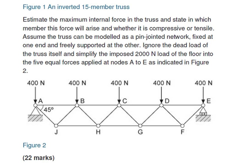
Any good mechanical engineers on here (maths content)
-
chilled76Free MemberPosted 10 years ago
Hi guys,
Any good mechanical engineers on here?
I’ve got a question on a forces within a truss question I’m having problems with (another maths teacher has put it in front of me, it’s from an old masters paper) and I can’t for the likes of me remember how to tackle the problem?
If so I’ll see if I can upload it as a picture.
Any help would be massivly appreciated. I’ve posted it on here as a lot of people on here often state they work in the engineering industry.
ahwilesFree MemberPosted 10 years agoin a previous life i used to design lifting equipment; trusses, frames, beams, etc.
was i ‘good’? – no, but nothing ever broke, even under proof-load-testing.
it seems i had a knack for simplifying problems that my clients seemed to appreciate. (no point providing calculations that a client couldn’t follow – or more importantly, that their insurance company couldn’t follow)
pic first, then help.
100mphplusFree MemberPosted 10 years agoThere’s enough Engineers of various occupations not just Mechanical, on here who have all probably calculated forces in trusses in the past, so if you load the picture we will then know if we can help you!!
ahwilesFree MemberPosted 10 years agowors – we generally went with ‘if it didn’t break when we tested it, and we’re selling it for more than it cost = it’s right’
(as long as it’s painted the right shade of canary yellow, and has some professional-looking certificates and stuff)
ir_banditoFree MemberPosted 10 years agoSounds like a simple statics calc. Balance the forces and the moments and you’re away.
Pic would help though…
wrightysonFree MemberPosted 10 years agoC’mon then? I won’t work out the calcs but I’d hazard a guess at fail or win!
chilled76Free MemberPosted 10 years agoSorry for the delay chaps, got busy at work then forgot I hadn’t posted it up.
 KahurangiFull MemberPosted 10 years ago
Can’t think exactly how I would have solved this at uni, would have taken lots of sections, written down lots of formulae and solved them simultaneously.
What I’d do now.. approximate it as symmetric (the DoF on the rHs is only necessary so that it’s determinate anyway), so split it in two. Resolve vertically at the centre and you can work the forces in beams Fcg and Fch so go from there…
Happy to be corrected
tomhughes46Full MemberPosted 10 years agoWaaaaay too tired to try to talk you through this one, as I will mostly likely cock it up, but from 4 mins,this outlines the method for something slightly simpler
kevjFree MemberPosted 10 years agoToo many unknowns hence ‘estimate’.
Member H-G in tension. With the figures provided, less than 800N.
chilled76Free MemberPosted 10 years agoIt’s estimate as the previous part shows a building floor on this and tells you to negate the weight of the trusses themselves and approximate the load as the 400N point loads on the nodes…. so the approximate is using figure 2 which I’ve included but not the original part as it wasn’t needed.
You can get a numerical answer using methods that are unfortunately 10 years in my past.
Anyone care to/bored enough to hand draft an answer with method and upload it?
thecaptainFree MemberPosted 10 years agoI used to do these at school, don’t have time right now but the tension at bottom centre is probably biggest. Consider the rotational force around one end (which must be zero of course). There are vertical external reaction forces of 1000N at each end, not drawn on
kevjFree MemberPosted 10 years agoTo be fair, there is an estimated figure based on simplified geometry and there is an exact figure determined by a far more complex combination of factors.
How many marks is this question worth?
The reaction at ‘A’ is different than that at node ‘E’. But the allowed displacement is unknown
In real life, the connections, member stiffness all contribute to load path analysis.
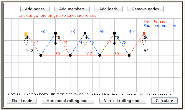
hexhamstuFree MemberPosted 10 years ago(not an exact representation because I didnt bother to do the angles properly…….)
http://www.jhu.edu/~virtlab/bridge/bridge.htmhexhamstuFree MemberPosted 10 years agoI’ve started hand calculations, but it’s late and i’m going to sleep.
aracerFree MemberPosted 10 years agoStarting from the middle and resolving vertically:
CH – 200.root2 compression
BH – 200.root2 tension
BJ – 600.root2 compression
AJ – 600.root2 tensionNow starting from the end and resolving horizontally:
AB – 600 compression
BC – 1400 compression
JH – 1200 tension
HG – 1600 tension…all done in my head using simple resolution (adding and subtracting) forces in vertical or horizontal direction at each pin joint. Diagonal members are at 45 degrees, so force in those is root 2 times the force in a vertical or horizontal direction (which are clearly both equal). Clearly half the load is taken in each diagonal at the centre, which is where I started.
My instant answer before doing the calcs was that HG in had highest load in tension.
aracerFree MemberPosted 10 years ago…have made a proper geometry using hexhamstu’s link, and pleased to find it gave the same answers as my hand calcs. Though I’d argue that my hand calculated answers are more useful as you can see the order of the calcs.
For those disparaging of my type I should point out that I’m a software engineer (though this is first year mechanical engineering stuff, which I studied as part of a general engineering degree).
chilled76Free MemberPosted 10 years agoThanks aracer, (and everyone else that’s responeded). Despite having a mechanical engineering degree I couldn’t remember how to solve the problem (use it or lose it I suppose)…. it’s been ten years and only the only remotely challenging maths I teach is A level core 2 which is all pure rather than applied.
Could you solve it by using moments about different nodes and forming simultaneous equations from your calcs?
Also, any chance of having a look at your workings? Seems a touch simple for 22 marks?
wrightysonFree MemberPosted 10 years agoJust remembered, all of that ^^^ is why we employ engineers.
chilled76Free MemberPosted 10 years agoHaving a look at it, isn’t aracers solution for a fixed bridge? Does your solution take into account it’s fixed at one end and free roaming at the other?
mrodgersFree MemberPosted 10 years agoYou can also solve it by considering half of the truss and taking moments about point C. This is a bit simpler as it means you don’t have to work out all of the forces in the other members, although you have to have a good idea which bar the max force is in first.
ahwilesFree MemberPosted 10 years agodammit, i was about to post my attempt, sort of similar to mrodgers’s, but considerably less mathematically ‘elegant’…
i was going to try and to rough-calc the effect of the 400N load at D, which must increase the tension, my initial estimate was that it would increase the load by 1/3rd.
but it’s now 10am, and i haven’t done anything useful yet…
tim41Free MemberPosted 10 years ago^^^ What mrdodgers said
Free body diagram , cut at centreline, consider left side structure.
Node horizontal spacing = L
Ignore point loads over the supports, these go straight into the reactions and don’t affect the structure. (You’ll get the same results but quicker without).
Reaction R = 1200/ 2 = 600
Moment at centre = (R x 2L) – (400 x L) = 1200L – 400L = 800L
Depth of structure = L/2
Bottom chord force at centre cut F = Moment / depth = 800L / (L/2) = 1600 tension
The other member forces can then be calculated by method of joints.
Hexhamstu’s solution is out by a factor of 1.5 because the angles aren’t right as he says. The truss depth is 0.75L, giving F = 800L / 0.75L = 1066
aracerFree MemberPosted 10 years agoNo – fixed ends would complicate things as you’d have to consider material effects (ie how much the members would expand and compress under load and the resultant horizontal loads on the support points). Which is why things like this are usually done with one unconstrained support – as indeed is the case for real bridges, though in the real world you also have other issues like thermal expansion to worry about. My working is done assuming no horizontal loads at the end supports, which is the effect of having one end freely supported and makes things a lot simpler.
Depends what you mean by simpler! Certainly less total calcs in your method and it’s very elegant, but I’d argue that each of the individual calcs for my method is simpler as you’re just adding and subtracting forces at each point, then it’s just a case of repeating at each joint (and actually I don’t need to do 2 of my calcs to get the load in HG). The other advantage being that it confirms the initial assumption about the member with the highest load. I’d probably give your method higher marks though (if I’d tried to do moments I’d have been busy trying to do them around point A!) The question has to be whether you could do your method in your head as I did with mine (just writing down the forces in each member).
First of all I should probably add details of where I’m resolving for each load:
C, vertical: CH = 200.root2 compression
H, vertical: BH = 200.root2 tension
B, vertical: BJ = 600.root2 compression
J, vertical: AJ = 600.root2 tensionA, horizontal: AB = 600 compression
B, horizontal: BC = 1400 compression
J, horizontal: JH = 1200 tension
H, horizontal: HG = 1600 tensionFor point C where I start from, clearly you can split the truss into two as everybody else has also done, hence half of the 400N load is taken by each half. Resolving vertically, the only vertical forces at C are the 400N load and the force in CH. Clearly the vertical component of the force in CH is 200N compressive in order to support half the 400N load. As it is a 45 degree member then force in the member is 200 / sin 45 = 200.root2 (alternatively you can consider that horizontal and vertical components are equal in a 45 degree member, so by Pythagorus the total load is root(200^2 + 200^2)).
Vertically at H the only forces are CH and BH, so the force in BH must be the same as the force in CH but in the opposite direction.
.
.
.when we get into resolving horizontally having determined the forces in all members with vertical components it’s just more of the same, but with more members involved and you just have to keep track of the direction of each force. As mentioned above it is assumed there is no horizontal force at the support. The most complex calc is probably horizontally at point B – for this I’ll use shorthand of tension -ve compression +ve (no idea if that’s the usual convention) so I can do it with formulae not words:
Fbc = Fab + Fbj sin45 – Fbh sin45
= 600 + (600.root2 / root2) – (-200.root2 / root2)
= 600 + 600 + 200chilled76Free MemberPosted 10 years agoFeel really thick now, that’s pretty simple once someone’s done it. Thank you very much, and thanks for taking the time to scan and upload.
Cheers gents.
Seems like you enjoyed this, I should upload a weekly Maths problem for discussion :-0
Next week… statistics

The topic ‘Any good mechanical engineers on here (maths content)’ is closed to new replies.