
MegaSack DRAW - This year's winner is user - rgwb
We will be in touch
I've been using CAD as a tool for nearly 20 years and I've fallen into a role where my regular Solidworks/Draftsight combo just doesn't cut it for the added landscape/presentation stuff so I'm having to learn Sketchup.
I've never used anything so counter-intuitive and it's doing my head in totally.
I realise it is really powerful and can do wonderful things but it's just such a different way of doing things I'm really struggling to adapt.
Anyone else had the same problem before or mastered it from no previous and can tell me to just get over it?
G
I use inventor/solidedge/solidworks but thought I'd try sketchup for a house extension, watched a first tutorial and thought how ridiculous it was to use so never even installed it...
I thought it was going to be great, I've even recommended it to someone on here based on the hype...
Let me know if you get the hang of it and if it is worth bothering with.
Every CAD user I've ever met can't get their heads round Sketchup.
Hate it. Hate it. Hate it!
When you're used to Solidworks/Inventor it seems so counter-intuitive!
I found it OK for sketching 3D freehand but anything even moderately complicated and it seemed a bit messed up and I really struggled to get any level of accuracy.
I modelled our attic extension. I found it ok if a little fiddly at times. I'm not a 'proper' CAD user though.
Unigraphics user here.
Sketchup is the worst. I tried to model a storage cupboard to optimise the space when fitting shelving/racking. I gave up.
Totally agreee with OP. Been using Catia v5 for years so I thought using sketch up to design my log shed would be simple......Gave up in the end and used Catia. The lack of accuracy absolutely appalled me, just couldnt work out how to apply constraints, dimensions or sketches etc.
I have a colleague though who has never used a serious CAD package and what he produces from it it really, really impressive.
Glad it's not just me then.. I've watched a few tutorial vids on Youtube and I'm stunned by the speed and accuracy that people can achieve.
No matter what I try and do it's never quite as simple as it seems. I guess it's just experience that's required but it's that bad I'm feeling like a total fraud as I'm not producing anything as I just can't use the tools "best" suited to the job.
G
Speeder - Member
I've been using CAD as a tool for nearly 20 years and I've fallen into a role where my regular Solidworks/Draftsight combo just doesn't cut it for the added landscape/presentation stuff so I'm having to learn Sketchup.I've never used anything so counter-intuitive and it's doing my head in totally.
Have you never used Pro/E, then?! God awful software compared to Solidworks. Took me ages to get my head around it, coming from a few years of Solidworks.
It's almost like they purposefully made it a real dog to use.....
We had a contractor leave our place, as even though he was happy with the pay/commute/work environment etc. he got offered a contract using Solidworks instead of Pro/E.
I looked at a few Sketchup tutorials and came to the same conclusion though - it didn't look that easy to use.
Not used ProE myself but one of the guys used it at the place I first learnt SW and it looked clumsy if quite powerful.
Solidworks has it's issues but at least it's consistent and makes sense. Sketchup just seems like it was designed by children. Good job it's free (or at least cheap)
There a 'Pro' version of Sketch-up - has anyone used it? I do wonder if its any better.
I thought sketch was marketed as a 3d modeling software rather than CAD software?
I've used it quite a bit, but I've never really got into proper CAD software - I guess that's the thing, if you come ot it from pro CAD software it's completely different, if you are a novice it doesn't seem that bad.
The Pro version works exactly the same as the free version, just with a few more functions. If you can't stand the navigation or the basic principles then you're not going to like Pro either.
Fwiw I find it's a useful addition to 'proper' CAD, used for initial architectural mass modelling and 'sketching' - still drawn relatively accurately and to scale, but I wouldn't use it for presentation drawings of any sort.
Its all about civil3d for landscape.
You just need to get your head around it, I use acad and revit on a daily basis and have used inventor and yes I agree it's nothing like any of these but once you get going its pretty powerful. Many of the architects we deal with use it instead of revit for modelling for the speed and versatility and it does give a good rendered image if you have the right pluggin.
I say stick with it and you might come round. I have the pro but find it doesn't offer much over the make version these days which is still free.
Modelled our extension with it. Easy enough that I don't remember any learning curve.
As the name suggests its a sketching program - knocking up quick drawings in 3 dimensions and the idea was it was a sketching programme for architects to mock up ideas before a proper cad monkey did real cad, as it was a programme that first appeared when architects were still using pencils. Its not counter intuitive - its totally intuitive in that its designed for people who aren't cad users. But it is counter-CAD if thats what you know
Funny you should post this..
I've just been playing around with it for the past hour, making a basic floor design of the place we've just bought. It's not too complicated a design, but has allowed me to print of several so the wife can plan out living spaces, but also lets us see what the planned extension (kitchen is currently in line with the rear of the house) would look like.
I'm planning on showing this to architects/builders etc, as I'm not that great at explaining stuff!
Also going to use with sparkies to figure out plug locations!
It's fairly easy once you get your head round it, but I reiterate - I'm a basic man using it for basic stuff!!
I did use it when building my son's bed - it was great for that as I could print out the sides and could annotate the real dimensions/gaps/spacing.
[img] 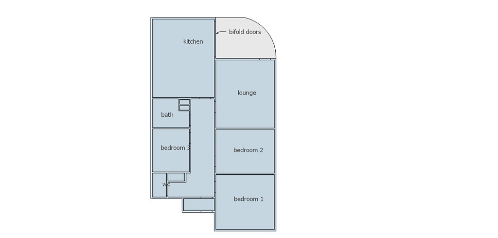 [/img]
DrP
I'm a basic man using it for basic stuff!!
As someone who makes the stuff that CAD wranglers design one of the things I like about sketchup is something that is easy to make in sketchup is easy to make with your hands, if its hard to make in sketchup then its hard to manufacture it too. It means at the design stage its creating resistance that the designer has to make decisions about how to circumvent, so an idea has to be good for them to be prepared to persevere with it. And if the thing they have to wrestle to design turns out to be time consuming or expensive to produce you can point out where that effort/cost has come from.
I've recently been playing with sketchup to try & model our house, work out where furniture etc can go & fit, thought it'd be fun...
Coming from an illustrator/indesign/photoshop background I'm finding it super awkward - given the hype I though it was just me, glad others have said this! So far I've managed to draw a floor in 3d & one sofa, drawing the 2nd sofa is giving me nightmares....
Theres the aspect of having to sort of un-know stuff if you're already a design software user - the other thing is.....
sofa is giving me nightmares
its for drawing houses - boxes made of flat planes with rectangular holes in. You can design much funkier stuff in in but you have to use it as the tool it is and play within its parameters.
its for drawing houses - boxes made of flat planes with rectangular holes in. You can design much funkier stuff in in but you have to use it as the tool it is and play within its parameters.
By sofa i mean this...
[url= https://farm9.staticflickr.com/8558/15790767026_92cc331333_o.pn g" target="_blank">https://farm9.staticflickr.com/8558/15790767026_92cc331333_o.pn g"/> [/img][/url][url= https://flic.kr/p/q4nNTU ]Screen Shot 2014-11-17 at 20.59.39[/url] by [url= https://www.flickr.com/people/15401902@N00/ ]zachw77[/url], on Flickr
You know there's an object library with a kerjillion sofas in it that you can just import into your model. Probably none quite as Simpson esque as yours though.
It can be counter intuitive if you're coming from a Solidworks, et al background, but you have to view it as what it is - a 3D sketching software, that can be used as CAD at a push.
I trained on Pro Desktop, and then Pro Engineer and I dislike them both intensely!
We use it as a teaching tool with the KS3 pupils as an introduction to 3D modelling software and CAD. There are some very good plugins if you look on Sketchucation - especially a ones from a guy called Fredo. They let you draw and extrude on curved surfaces, skin objects, and do a host of other useful stuff.
You can also get a plugin to convert files to .stl files, so we are using it with our 3d printer with a lot of success.
Arah the old "i've designed this in CAD ca i make it?"
Usally with the reply how do i hold it? and how do i mill a 2mm internal rad 30mm deep?
Some the new free autodesk stuff is looking good. The free cam software includes a post processor! Bit different to powermill mind more feature cam based.
You know there's an object library with a kerjillion sofas in it that you can just import into your model. Probably none quite as Simpson esque as yours though.
Fair point, but are they the right size....
& to be honest that shape shouldn't be hard to draw...
I thought it was just me. Really frustrating and I'm not a CAD user.
Whilst the CAD experts are in, how easy would it be to model the socket part of these? I want/need to 3D print one on the end of a cylinder so that the joint comes out axial rather being bolted to the side of the tiller and coming out radially.
Just wondering whether it's worth the effort of learning it.
[img]  [/img]
[img]  [/img]
Tinas - if you can imagine it, you can model it. Whether it's worth making a model vs just sketching it on the back of an envelope? It will show you how it all goes together and whether it gives you any clearance issues but if you've thought about it enough that is unlikely to be a huge problem. Depends really on how complicated it will become as an assembly who you're taking it to to make it.
What is it anyway?? I assume from "tiller" that it's boat related.
G
See... For that sofa I'd draw a rectangle, pull it up to make a cube. Then on the to face I'd draw a smaller rectangle then push that down....
Dr P
Yup that's what I did, it still made it painful, then when I tried to move it I just kept grabbing the edge and changing the size...
Speeder,
Yup, it's the universal joint from a tiller extension to allow you to steer from the side/front of the boat, typicaly they come out the top of the tiller and into the end of te extension. But that leaves a 1.5" stub of tiller projecting out which catches the mainsheet causing problems (usualy an early and very cold bath).
The idea is to fit the joint into the end of the tiller so that there's nowhere for the rope to catch. Doing this by incorperating the lower scoket bit into the end of a cylindrical bung. At it's simplest it'd be 4 extrusions, a hollow cylinder, a solid cylinder, a large three sides of a square hole in a cylinder and a small 3/4 of a circular hole in a cylinder end to end.
I mocked up a prototype from an old bung and epoxy but it split eventualy. I reckon there's enough demand to make it worthile 3D printing them for beer money.
I have to admit to not having a clue what you'e talking about and can't picture it at all but I'm sure there's a lot of thought that's gone into it already and it wouldn't take long to convert into a design.
Be aware that 3D printing isn't generally particularly strong due to the fact its just laminated plastic so it's weak between layers and this may impact the way you'd want to layer it up. Having said that a moulded part would likely be too expensive to bother without volume and it may be the only way. People have started 3D printing carbon mind and that may be an avenue to explore.
Yup that's what I did, it still made it painful, then when I tried to move it I just kept grabbing the edge and changing the size...
You need to make it an "object" it will then become a separate entity within the model.
Yup that's what I did, it still made it painful, then when I tried to move it I just kept grabbing the edge and changing the size...
You need to make it an "object" it will then become a separate entity within the model.
It's all about the 'outliner' tool - start using groups and components.
It's all about the 'outliner' tool - start using groups and components.
Once you have done this you can then create new layers and locate groups there, "furniture 1" for example. This allows you to make different layers visible or not, and lets you try out multiple different layouts.
All drawing [b]MUST[/b] be done in the default layer, not the custom layer that you have created.
tinas - i always thought you were an engineer..?
anyways as has been said please dont use a '3D printed part' for what you describe..
Whether you use depose or frittage it will break if your bodge broke.
Anyway to describe it - i have no idea what you are talking about in boat terms but if you can maybe do a sketch of what you want you can 'design' a part that is machinable? Even if its split, if its alu then it should hold better for your use..
Tinas I know exactly what you are describing. Were you thinking a plug or a cap?
You'd need to know the diameter of the tiller and measure all the dimensions but it's a pretty easy model.
tinas - i always thought you were an engineer..?
Yup, but we have offices full of CAD darfters, we just have to sketch out what we want and sent it off 🙂
Tinas I know exactly what you are describing. Were you thinking a plug or a cap?
Plug.
I reckon it can be made strong enough, the prototype failed because it really was a bodge, I drilled the original 'plug' and split it, then gued it arorund the shaft of the joint, so it was pretty crude. If I did it properly the whole thing would sit inside the tiler so that most of the loads were just compressiing it against the sides rather than trying to shear it off.
I have no idea what you're talking about, we're outside my sphere of work. I picked 3D prnting as it's relatively cheap to have a one-off bit made, I don't think in this case the loads are particularly high. Machining it from a block of something would probably be better, but would be yet another thing to do instead of just e-mialing a file to someone with a 3D printer.Whether you use depose or frittage it will break if your bodge broke.
I suppose an alternative would be to just make it out of layers of ~4mm acrylic sheet glued together.
In fact I might just do that as another 'prototype'.
Is there enough flex to allow the tiller extension to pass backwards across the transom?
I find it useful to mock up ideas and then move them around and look from different directions. I used it to calculate the materials for the shed, tub and sauna. I don't think I could use it for anything complex or requiring accurate measurements though.
[img]  [/img]
[img] https://lh3.googleusercontent.com/HiRnNjTrvtHD-yl2jvRK132Vl_o4x22EE8sph7F_Kk4=w1011-h823-no [/img]
[img]  [/img]
And the nearly finished result looks similar (apart from roof angle where I forgot to measure garage roof level before drawing)
[img]  [/img]