Cateye ABS35 to see if there is enough room to facilitate one of these high power upgrades. I'm out of luck as the driver would never fit.
[b]Spongebob[/b], why not mount the driver externally, I'm thinking of mounting my driver pcb's and power switch externally...the power switch on the bars, and the drivers next to the battery?!?
Stephen your commuter/head mounted light shows great promise, small package size and conveniently powered..should be a real winner, was it a 1W output??
3x Cree LEDs plus driver on a single board
This will be [b]VERY[/b] popular (especially if the board had flying leads already soldered on).
I.e. make it as near 'plug and play' as possible.
It appears to be what most people want, especially those who don't have either the confidence, motivation or time to bugger around like a few of us on here
3x Cree LEDs plus driver on a single board
Sounds good, for what housing / optic?
http://www.ultraleds.co.uk/ultimate-mr11-acdc-cool-white-bulb-p-1764.html
£7.82 and they claim it equals 18w halogen. Not anywhere near as bright as the Lumicycle upgrade, but I have tow lamps and for the money....
DoctorRad: Not sure yet - suggestions appreciated! I was initially thinking a circular housing / lens but OTOH a 'strip' would mean less PCB waste. I think my main issue is going to be whether FR4 would suit this or if I need to look in to MCPCB. I have read app notes that suggest thin FR4 with plenty of thermal vias can do the job but I'm not sure if that would scale for 10W+ of LEDs.
I need to order some 0.8mm PCBs soon so I'm going to add a few variants to evaluate. Not likely to be before February when I get some results though!
Spongebob: Based on their claimed 150mA power draw that looks like 4x 0.5W LEDs - certainly at 12V that is only 1.8W total power. Depends on the efficiency of the LEDs of course but I suspect you'll get as much light from a single decent power LED at a similar overall power level. Also, they talk about 'wide angle' - unlikely to be suitable for a bike light I would suspect.
Hi, does the driver with dim mode reduce the current draw from the battery and therefore increases run time or does the battery draw remain the same but some current is used by the resistor and therefore a reduced current gets to the LED's? Tks.
Hi DaveGr, the dim mode uses less power from the battery. On testing I'm finding I get around 540mA in dim mode for the 5W (970mA) driver. Your input current should drop proportionally.
All this power talk is very misleading . . . use drive current . . . it's the only thing that is constant with differing LED's and configurations . . .
$0.02
Fd
Fergus: Very much agreed. Unfortunately most LED manufacturers quote power... To be fair, Cree and Seoul don't push power ratings but many of the 'lower end' companies do.
I wish there was a simple answer but I think quoting power has become too established - despite the fact the power ratings quoted not only vary between colours but are wrong anyway...
The simple answer is to state the following
drive current
max input voltage
min input voltage
driver drop voltage
max input to output voltage differential
efficiency curve
Power doesn't come into it until you know what load you are driving as you know.
My conversion using your driver is 10W power consumption, 2W light output, 8W heat output but uses your 5W driver . . . which isn't a 5W driver at all it's a 970mA driver . . . which is more confusing ?
Fd
This is why I try and quote both and explain in my listings. This isn't as relevant to 1A LEDs as it is rate to use power for these. However, you won't find many 350mA and 700mA LEDs not described as being 1W and 3W respectively. I try and make it clear these are drivers *for* 1W or whatever LEDs, not that this is the actual output power.
I think next time I re-list I will revise the descriptions and definitely for the 970mA drivers remove the power reference. The 670mA ones are marginal while the 330mA ones I feel quoting 1W is valid as this usage is most common at this drive level.
Quick question - do both the XRE and XPG PCBs have the two pins in the centre for connection? If so, are they absolutely central and what is the spacing?
I will be able to order some more PCBs early January and I've had an idea to make a driver which solders directly to the pins from the LED PCB with power and control inputs at the other end. This should make the conversion much easier.
they are in the middle Steve
[img]  [/img]
@ BlackCat
If you solder the driver board directly to the PCB, wouldn't that get in the way of the heatsink?
Plan is to have two terminals on one end of the PCB on the same pitch as the holes on the MCPCB. You'd then mount the driver PCB at right angles to the LED PCB with pins long enough to pass through the heatsink. Other option is similar but have the driver parallel to the LED PCB but with long enough pins to keep it clear of the heatsink. Not sure I'll be able to get the output pins central to the board though so the end-on approach is probably best.
Also wondering about the option of getting some custom-made heatsinks. Should be a fairly simple turning / milling job from some 32mm alu. Depends how much demand there is but based on the time saving over modifying the one Chucky used it may be viable. Can anyone give me a decent measurement for the flat?
Must look at getting one of these enclosures myself to play about - anyone know of a cheap source? Even the plain enclosure is £35 from Lumicycle!
Any thoughts on the following as aiding cooling ? There are two types, one solid (mk1) and one vented (mk2) which is similar to the ones on [url= http://cgi.ebay.co.uk/RC-540-Motor-Upgrade-Vented-Alloy-Heat-Sink-heatsink-B_W0QQitemZ200374783340QQcmdZViewItemQQptZUK_ToysGames_RadioControlled_JN?hash=item2ea7448d6c ]Ebay[/url]. The manufacturers web site doesn't give dimensions apart from "fits electric motors".
[url= http://www.hpiracing.co.uk/piw.php?partNo=ED010411 ]Clip-On Alloy Motor Heatsink[/url]
While I'm thinking on, are there any spare Cutter PCBs / Optics floating around and if not do you need to order a single LED on the MR11 PCB or do you need to order three LEDs plus the PCB? The Cutter site isn't that clear... Best invest in my own stuff if I'm going to look at doing stuff for these properly!
Dave - Would certainly help. The problem with the standard Lumicycle housing is that it is 'flat'. In general, the more surface area you have the better the heat dissipation. Only question is whether they will fit the housing although as the one with a fan is for a 25mm fan and the diameter looks bigger than that then maybe...
DaveGr - I used something similar on my conversion, look back through the posts for pictures. It seems to work very well, although I've only been out in the freezing weather which obviously helps. They [i]should[/i] fit exactly as a 540 motor is just the right diameter, however I've had two different designs supposedly for 540 motors but when they arrived they were different diameters.
BlackCat - you only need x1 LED in the cart to set the type required on the MCPCB, then select however many boards you want.
Blackcat - The board we're using for the conversion is the XPGMR11T with 3 x 1w Cree LED's. Will the 970ma driver work with this?
[url] http://www.cutter.com.au/proddetail.php?prod=cut937 [/url]
Got my board today Blackcat (with wires already souldered to save my cack handedness knackering it up). ACE! Ta very much.
SB: That board uses the XPG which is fine up to 1A.
To those who replied off-list, I've not forgotten, just snowed under at the moment!
Hoping to have a lumicycle-specific driver late January and a simple test-hack to see if I can run power LEDs on standard PCB laminate for an all-in-one.
Have a good one all - off for a few days now.
I've just had a mare soldering on the connectors on my XPG board. They peal up so easily. The ERX versions were much much more durable when trying to get the board back into the housing. as luck would have it I managed to peal up the track scrape the black off and solder carefully to that. Not perfect but it's holding for now. All in all, I'm not really impressed with this new board and will be ordering XRE Q5's from now on as I'm happy with the 4 can's done already using this method and I don't think the XPG MPCB is quite up to the job.
That's a bit odd - I soldered up an XP-G triple MCPCB a wee while ago with a burnt out crappy soldering iron tip, and it held up OK. I'm a novice solderer, and was using crappy equipment, so I reckon you might have been a bit unlucky. I've since redone it with a new clean tip and it was a million times easier to get the heat where it needed to be rather than sitting the tip on the pad for a minute or two before the solder would melt. Everything was getting hot except the bits I wanted too!
Anyway, have my first conversion all done and dusted now. Big thank you to Chucky, fergusd and others for the help. Have ordered a quad XP-G from Cutter, and the other bits required to convert my other Lumi can too.
Gray
I'd considered a quad conversion too, however I couldn't get the right battery/driver combination.
x4 XPGs at 1000mA should give a total Vfd of about 13.2V, if you're using a 14.4V battery you'd need a buck converter like a bFlex or one of BlackCat's drivers where the input voltage must be greater than the output voltage.
However, the bFlex margin is recommended at +1.1V over Vfd and BlackCat's is +10% over Vfd. This means the lowest recommended battery voltage is 14.3V for a bFlex and 14.6V for a BlackCat. It won't take long for even a freshly charged battery to drop below these figures and therefore send the board out of regulation. This would mean losing dimming capability on the bFlex, not sure of the implications with a BlackCat though.
I'd also considered a x5 XPG which is even worse! However it can be overcome using 2 drivers. I had planned on using a Hope HID housing to fit it all in, this may be a bit of a squeeze in a Lumi halogen can though.
Unless you got a faulty one I don't think there is any issue with the XP-G MCPCB . . .
I've soldered a number of these now and have had zero issues . . . however I am an experienced solderer and have the correct gear . . .
I suspect you are overheating the solder pads, probably because you are using too hot an iron and not using it properly (no offence) . . . probably keeping it on the joint for far too long
I use a small tipped iron (1.5mm width) of about 20W power with 1mm solder and can solder these joints onto the MCPCB in about 1.5 second . . . you must use a clean iron tip (use a damp sponge to clean it) and apply the iron to the joint with the wire already inserted, leave in place for about a second then touch the solder onto the joint (not the iron), the solder will melt and the flux will clean the joint and the solder will then flow onto it very quickly . . . then remove the iron . . .
It helps to pre-tin the wires (ie. get some solder onto them before you try to solder them into the board - makes the process quicker - again this should be done with a clean iron and quickly)
large iron tips don't help, hot irons don't help . . . and like all PCB's if you overheat them they will de-laminate and the pads will come off . . .
You can usually file down iron tips to give them a second life . . . but ensure that if you do they DO NOT have the heating element as part of them (most don't but you can see the danger)
Finally got my cans converted...BIG thanks to Chucky(AKA Racing) for the guide,ordering,answering dunbass questions, and Jonathan B for the soldering skillz!
XP-G's running with Blackcat 970mA drivers,8mm alloy heatsink and a lot of elbow grease
Lumicycle cans[img] http://www.flickr.com/photos/nockmeister/4288605085/ [/img]
http://www.flickr.com/photos/nockmeister/4288605085/
[img]  [/img]
they look great with matching heatsinks.
glad it all worked out well
I've had to send my XPG board back as the tracks pealed off the board. THe XRE is as good as ever and I've replaced it with an SSC for now. Still need to find someone with a proper internal heat sink.
Converted one of my Lumi cans using Chucky's instructions. Triple XPG but with an XPE optic and a 650ma driver board from black cat.
Works beautifully, does get a little warm on the can when tested in a warm house(the house was also not moving at the time), but nice and cool when on the bike.
Converting my Lumi HID next.
Right, checked out the driver and the heatsink on ebay, to no avail, and I'm not sure what led's and optic to order from cutter?.
My lumi's are the old 13.2 battery, and it's the standard cans.
Help!.
Anyone?
I think you need to start at page 1 and go from there.
The guy who makes the driver board has even posted on here & can probably be contacted through his profile, the heatsinks are flywheels from a nitro r/c car - even if you can find the link to a dead eBay item you'll get a description of what you need (I think someone posted a sketch somewhere too)
There are also several replies to the 'what optic & LEDs' question.
I believe that your battery will be OK, but am not an electrical genius (not even an electrical half-wit) so I'd ask the bloke who supplies the drivers (I think his name is black cat on here) when you e-mail him....
Nobeerinthefridge
mail me (it's in the profile) and i'll tell you what LED and lens to order.
Dave
I have just changed my 3W driver for the 5W version with the low power resistor on the board. Can anyone explain how I wire up the board to a switch to give FULL POWER - OFF - LOW POWER. The negative pole of the battery needs to be connected to the - connector on the board for full and to - as well as to A for low power. I have a 3 pole ON-OFF-ON switch and can't work out how to wire it up. Do I need to get hold of a different swich?
I don't think you can use the switch to switch on and off. I had it so that you had to unplug the lead to power down.
I connect the neg from the power connector to the centre tab on the switch together with a wire to the neg on the driver board. The connect from the 'A' connector on the board to either of the outer tabs on the switch. This allows you to either switch the 'A' wire in or leave it out just have the neg from the power connector go to the board via the tab on the switch.
[img] 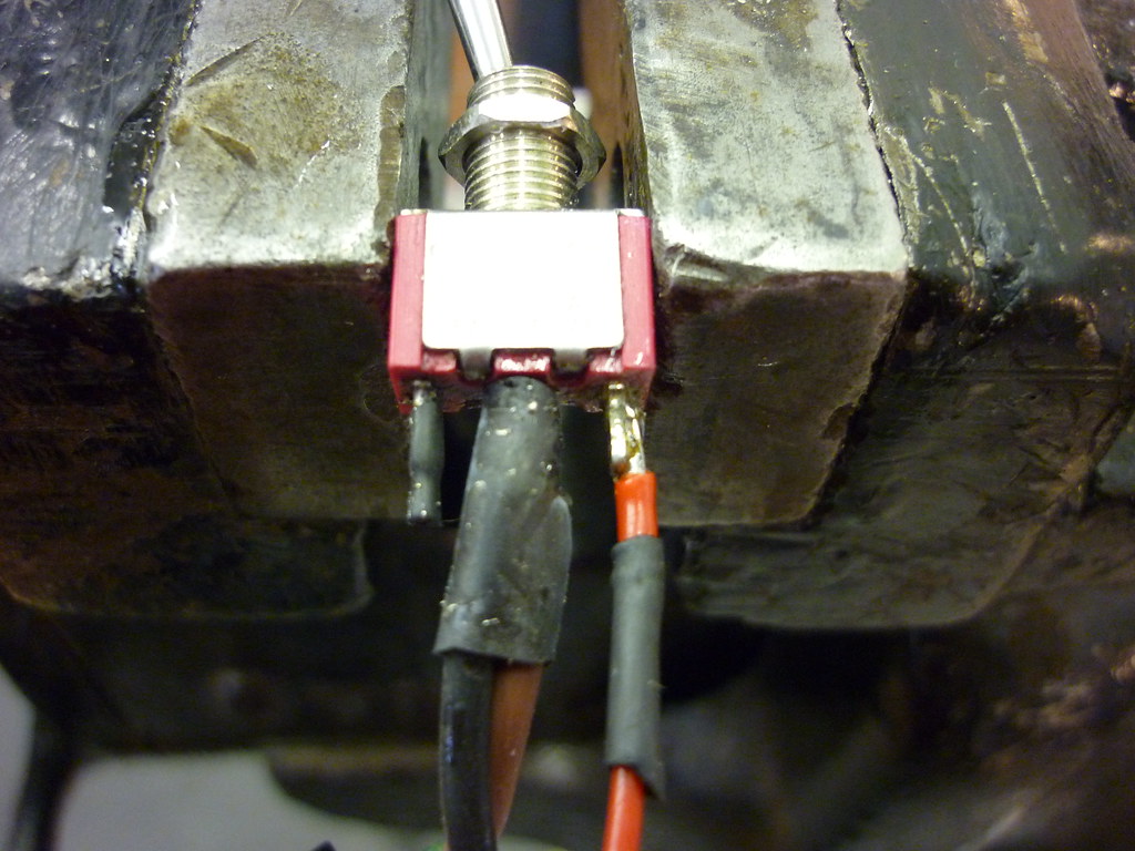 [/img]
here the brown is from the connector and the black goes to the neg on the driver. The red goes to the 'A' on the driver board.
Sorry I've been missing from the board for a while guys, back now if you have any queries.
The drivers are still available but in response to comments on here I've changed the descriptions to remove the reference to power ratings. Trouble is that since I did that sales have slumped so I suspect people haven't thought to look in my eBay shop and locate the new items....
The store URL is http://stores.shop.ebay.co.uk/Black-Cat-Technology or my website at www.blackcattech.co.uk currently just links direct to my eBay shop - until I get time to create a proper website that is! The drivers are in the 'Power LED Drivers' section.
I think squeekybrakes contacted me independently about the switch issue. What you call a three-pole switch isn't. A pole on a switch is one independent switching mechanism, not a reference to the number of terminals. So a switch that has one common, one normally open and one normally closed is a single pole, double-throw switch. (SPDT) - in other words, you have one independent mechanism that can go two ways. A double-pole switch has two switching mechanisms that have no electrical connection between them.
To turn a dim-mode driver off you will need a double pole switch - unless you use Chucky's method of just pulling the plug. You also need a switch that has a centre-off configuration. In other words, there is one 'setting' were no electrical connections are made in the switch. You have one pole of the switch where both normally open (NO) and normally closed (NC) are connected to the 0V power supply, and the common (C) is connected to the 0V / PWR- terminal on the driver. This means that for either direction of the switch power is applied but for the centre-off setting it is removed. Then one side of the other pole (can be NC or NO) is connected to 0V and the common to the 'A' terminal. This means that for one setting the 'A' terminal is pulled low and for the other it is left floating. Therefore, one way you enable dim mode and the other way the driver runs at full power. In the centre-off position the 'A' terminal level doesn't matter as there is no power to the driver.
I'd meant to get hold of a lumicycle can and look in to getting some heatsinks custom-made. Indeed a few people from here did offer to lend me theirs but due to pressure of work I didn't get around to replying. Apologies to those people for ignoring them!
Hoping to have a new version of the driver in about 3 weeks now - again delayed as I had too much to do. This one will have shutdown and half-power modes built in and is designed to sit better inside the can.
my solution..
[img] http://www.flickr.com/photos/nockmeister/4331461906/?rotated=1&cb=1265328024153 [/img]
I've finally received the new driver PCBs - the fab. that I use had a few problems so delivery slipped. I've done a basic 'systems test' and it works OK.
These have connections to allow both shutdown and half-power modes to be selected from a single-pole centre-off switch. There is also facility to fit a thermistor to reduce the current when the temperature rises - this isn't ideal as it slightly reduces the maximum output but should be useful.
I'm working on getting some heatsinks made and hope to offer an upgrade 'kit' of driver, switch and heatsink shortly.
Right, guys, a bit of help is needed! The lumi-specific drivers have been ready for a while but I'm struggling to get heatsinks made. I was hoping to get some made at work but it seems that 'internal politics' (i.e. the turner trying to buy the place) has meant that isn't possible.
Can anyone recommend a good / cheap machine shop that does basic CNC stuff? I was intending to get these made professionally anyway but was hoping to get prototypes made at little / no cost just in case I ended up with a load of heatsinks that didn't fit...
A place near me might help
mail me on eastham8ATaolDOTcom
and i can approach them and see what they can do.
can't promise owt, but i'll try.
some guys off here have lathes, maybe they could help?
HELP!!
Having just resurrected this from the depths of the forum, I want to finally sort my conversion out this weekend but am a bit stuck.
From what I have read above, I was under the impression that I could use a single pole switch with on-off-on positions to set the light up to be low-off-high with a 200k resistor soldered into the 'A' control point on the driver board. Is this the case?
If it is, then can someone describe how I can do this as I don't understand what layout I need.....? A diagram would be great.
I have also e-mailed Chucky(vortex racing) directly as well as Black Cat Tech who sells the drivers, but I thought I'd see if anyone was about on here who could give me some pointers.
I bought the 'B' type switch from Maplin:
http://www.maplin.co.uk/Module.aspx?ModuleNo=2341
in anticipation of it being possible, but might have to resort to the normal switch and just have on-off if I can't find out how to do it.
I'll need to get a new switch as the Lumi one appears to have stopped working after trying a 35W bulb one evening on a ride.
Hi Fella,
Nope on the old BlackCat drivers you needed TWO switches, one for on/off, the other for half power. I missed the update that Stephen(BCT) added, his latest driver is the future! er saying that it's not a big issue to flick 2 swithces 🙂
PS...the conversion is WELL worth it!!
Oh I have a couple of new switches over that you can have for £2.50 posted!
Oh Poo!
I thought it was possible, from this on page 6 (posted by gray):
If using the standard Black Cat driver, then it's easy enough to use a SPDT switch such as the Type B Maplin one to have a configuration such as off-full-half (where the off mode is a soft off, so technically not quite as off as unplugging the power cable, but effectively the same), by using the control terminal and a resistor.
And Trout said on page 4:
.there is also the option with a 3 pos switch to short direct the neg to A missing out the resistor as a soft off too
I must have misunderstood......
I think I'll just do it as full power/off. Gotta go into town on Sat for some shopping & there's a Maplin that I can get a new switch from. Thanks for the offer though.
back from work now, got your mail and will respond, but as the lads have said you can't have a on-off-1/2 setting with the old board.
I used the switch to switch from 1/2 to full and just pulled the lead out to switch off.
at this rate you might have it finished for summer solstice 😆
HA HA!! At this rate I think you might be right. So long as it'd done by the 24/12, that's all I'm worried about.
Need to nab a soldering iron/solder from work for the weekend and should be able to get them sorted (so long as Maplin have the switch I need in stock!).
I ended up getting some heatsinks made, as I couldn't find any of those nitro car flywheel heatsinks on eBay (or anywhere else for that matter).
Can't remember the exact details, but it's about a 6mm back plate with a thin shell that comes forward to fit snugly against the Lumi can. Should provide a bit more surface area for heat dissipation. Looks like this:
[img] 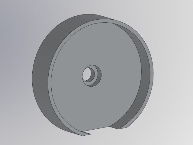 [/img]
seems perfect. is the relief at the bottom to clear the nut in the case?
Yeah, the relief clears that flat edge in the bottom of the can (same as filing the flywheel down).
I had them made with a slightly oversize outside diameter so I could wet/dry them down to a really snug fit.
Either that image was saved before I finished the design or the angle makes it looks shallower, as in real life, the thin shell is pretty deep, and provides a decent contact area.
I'll probably do some build pics (if I can persuade the other half to do the soldering this weekend) and pin my result to the end of this thread next week - perhaps with some garden beam shots too.
I feel that I should point out that I've been running 2 sets of 3 x Cree XRE lumi halogen conversions for 2.5 years now.
They have no 'heatsink' at all, just the outer can, which is coupled to the led plate just by a snug fit around the edge with a bit of heat transfer compound.
I've had no heat problems in those 2.5 years and they still work as well as they did when I made them.
Yeah, probably overkill but I'd rather be safe than sorry.
yes you can have off hi low with the old board and the switch stumpy has .
I just need to have a look at one of mine that does just that .
Aaaaaarrrrrrrrrrrrgggggggggghhhhh! Salvation!!
I would be extremely grateful if you could investigate how I can do this trout, bearing in mind that i am a complete numpty when it comes to electronics....!
[IMG] 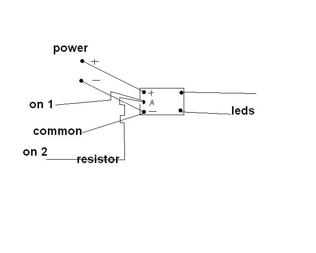 [/IMG]
I hope I have this right .
both power connections as normal
common on the switch to negative
one of the ons with the resistor to A this is the dim
the other on direct to A this one is the soft off
and with the switch totally off this is full power
Also soon there will be an even easier way to do the mod
Excellent! Thanks for that!
Excuse me for being thick, but I take it that 'common' is middle position on the switch?
So, the switch as described above will be off at one extremity, on full in the mid position & the dimmed in the other extremity?
yes usually the centre terminal is the common one and the outers are the seperate on`s
so yes in the diagram up would be off
middle would be full power ( but technicaly the off position of the switch )
down would be dim
Sorry for being late to contribute to this.
Either version of the driver can have the three-mode function but you need a different switch. It is easier with the 'standard' version as you only need a single-pole, centre-off switch. The 'Dim Mode' needs a double-pole, centre-off and more complex wiring.
I'll put together a comprehensive guide to this tomorrow - bit late at the moment! However, Troutie's instructions for the standard version are spot-on.
BTW, Stumpy, your heatsink is pretty much exactly what I was looking to get done. I have managed to get one prototype made and will try and post a picture tomorrow also. I should be able to get a few done as a favour but if hundreds of people want them then I'll have to look at other options! Basically, the new driver sits inside the recess on the heatsink.
I'm also getting a prototype made of the LEDs and driver on the same board - currently looking at 3x XREs at 700mA as I doubt standard 2oz 0.8mm FR4 would handle any higher power than that!
As for using the LEDs without a heatsink, all I can say is NOOOOOOOOOOOOOO!!!!!!!!!!!!!!!!! I'm amazed this has worked at all! I have three Seoul P4s attached to an old PC processor heatsink 50mm x 60mm with fins and that gets too hot at 1A - certainly too warm to hold and at the point where you would be shortening the life of the LEDs. Without a heatsink they will get seriously hot and probably have a much reduced life.
(My setup does show the benefits of moving air cooling - with the fan on the heatsink is cool to the touch!)
Hoping to find some time later today to do this. Cheers for the 'common' clarification, trout.
BCT, I fiddled around with a few ideas on Solidworks & have a friend with some fairly decent machining capabilities. He's done me four to get started. I'm planning on converting one light for me & one for a mate, then if it works ok we're gonna do our other ones at some point. (Don't know if you are aware but the common Lumi set-up is two lamps - 1x20w + 1x12w).
I can e-mail u over the pdf of the drawing I did if u want next week? Only thing to note is that the outer diameter is slightly oversized so I could reduce it down to a tight fit once I'd tried it for fit. The LED board is also a snug fit as I wanted max contact.
With regard to heatsinks in general - I wonder if a very snug fitting LED board allows enough transfer to the can on it's own?
My approach was a bit more simplistic! Drew a basic sketch and gave it to a friend at work and asked him to make that fit in this. (i.e. the lumi case)
I'd gauge that even if the heatsink board is a good fit you are still trying to transfer a lot of heat via not very much metal so the area under the LEDs themselves will still get very hot as the heat can't 'wick' away.
If you are always cycling then you may get away with it from the air flow but if you sit around with it on full then overheating is surely unavoidable. To be honest, I doubt the lumi case itself is a good enough heatsink when stationary when the LEDs are on full power.
Might be worth noting that unless they get *really* hot you aren't going to 'blow' the LEDs, but the higher the die temperature they run at, the shorter their life. A general rule is that under 60C you can get 50000 hours+. Many can take 120C but your life may be reduced to a few thousand hours. However, daft as it sounds but you may get slightly longer battery life this way as the Vf usually drops with increasing temperature.
The 'life' for LEDs by the way isn't until failure, they gradually drop light output and the life is quoted as when they drop to 2/3 initial output.
I wasn't aware that the common setup was two different power lights but I guess with the two power options with the LEDs then you can have both full power and have more power options.
Apologies if this doesn't work, just signed up to FlickR to put some photos online. (Virgin seem to have messed up the old NTL FTP settings so I can't get on to my webspace at the moment...)
Photos of the new driver and heatsink arrangement:
http://www.flickr.com/photos/50439158@N02/4631185669/
http://www.flickr.com/photos/50439158@N02/4631185715/
I've tried to get maximum 'height' for the heatsink to allow maximum transfer to the case.
That looks like an ideal solution - nice & compact which is just what's needed.
Just realised I forgot to get any resistors so not gonna be able to do the conversion for a while - bu66er. More delay.
That was the aim! There were a few comments on the original conversion about the driver being hard to fit in and possible shorts so I thought it would work well to have it tucked away instead. The only issue I'm looking at is making sure there is no chance of it shorting against to back of the switch etc. When I am done testing I'll probably sell this as a complete kit with a new switch and socket pre-wired and including the heatsink so all people will need to supply is the LED board and lens.
The new version also has the resistor built in while still allowing shutdown so no problems like that! 🙂
Steven did you have a look for bits that would allow 1.5 amps drive current do they exist yet .
Hi Troutie, I've got some boards on the go at the moment that may allow me to do this. I'm using the Zetex ZXLD1320 which can do 1.5A. Trouble is that it is in a package which shall we say may be tricky to solder... (No pins, solder pads underneath and also stupidly fine pitch)
If that doesn't work out then there is a design out there to allow the ZXLD1360 to drive an external pass transistor to increase the current output. This will add to the cost and I think may reduce the efficiency. Otherwise, National do a few controller chips that are designed to work with external transistors but their solutions seem to have to be tailored closely to the intended supply and load while the Zetex drivers are much more flexible.
No immediate ETA on this I'm afraid - boards are due mid June but I'm being pestered to finish a reef aquarium lighting system ASAP so I'm finding it difficult to get other stuff done. (Thus the fact the new Lumi drivers are taking so long to get on sale....) If anyone fancies a bike light with 6 banks of 5 XPGs running from 24V then I may be able to help....
Just to let you know that Diodes / Zetex have just announced a new chip, due in the next month or so, that does both 1.5A and proper thermal limiting, plus it comes in a package that doesn't need expensive automated equipment to solder. As soon as they become available through 'the usual suspects' I'll get some prototypes built up.
Hi,
I have read through this and other threads and realise that developments are continually moving on, so could still do with some advice please.
I have two sets of halogen lumi's to convert, 13.2v 4 a/hr NiMH batteries.
Is the output of one can converted = to or better than a pair 20/12 halogens?
Triple or Quad XPG kit from Cutters ( http://www.cutter.com.au/proddetail.php?prod=cut756), is this the way to go and all I need?
Any other suggestions?
Cheers
Paul.
I'm in the process of doing the conversion of a couple of halogens, and am getting some simple heatsinks made up as that RC part at the beginning of the thread seems to have been discontinued.
I can pretty easily get a few more cut. Anyone interested? It'll be nothing more than an aluminium disc 33mm diameter, 5mm thick.
I'd expect to have them in 1-2 weeks time, and would want £7 (inc P&P) to cover costs, hassle and the man-with-the-lathe's beer fund.
Email in profile if you're interested.
PaulB
I wouldn't advise a quad XPG with a 13.2V battery as you'll struggle to get a controller that will operate properly through the whole of the battery's discharge curve.
Check out the voltage requirements for both the maxflex and bFlex boards on Cutter's site for more info.
I'll try and give a simple explanation about battery voltage vs number of LEDs you can drive.
There are two basic 'ways' an LED driver works, Buck mode is where the output voltage is lower than the input voltage. Boost mode is where output is higher than input. In both modes where you have output close to input it causes the circuit problems. In essence, both types store charge in an inductor for part of a cycle and release it for the other part. Buck regulators would spend most of their time charging the inductor leading to overheating problems. Boost regulators would only need tiny blips of charge leading to control problems. (And poor efficiency)
There are devices know as Buck-Boost regulators which can bridge this gap but these are generally much more complicated circuits requiring more components and usually coming with an efficiency penalty.
If you were using 4 XPGs then your combined Vf would range somewhere between 12 and 14V (based on a single Vf of 3.0 to 3.5V) NiMHs can vary from about 1.4V fresh off charge to 1V or less when discharged. I'm assuming the 13.2V pack is 11 cells so 15.4V down to 11V or right across the Vf range of the LEDS.
Three XPGs would be 9 to 10.5V so if they were at the top end of the scale they would challenge many drivers with your batteries fully discharged. I can't comment on other drivers but mine do keep working down to the point where Vin is just higher than Vf but generally at a reduced current. I wouldn't advise this for extended periods though as it will be overloading the chip. However, as your voltage would generally be well above the LED Vf then you'd have no problems at all.
I don't mean to be funny BlackCat but your 'simple explanation' is anything but, and I know what you're on about. 😕
Bottom line is for a 13.2V NiMH: 4 XPG bad, 3 XPG okay
I run a 3 XPG Lumicycle conversion with a bFlex driver and a Hope 14.8V 2.4 Ahr Li-ion battery, it runs at full tilt (1A) for about 2.5 hrs. It's a very capable helmet lamp.
Better Alternative,HEALTHIER & just as GOOD. I Won't look back
Guys you need to try these E-Cigs out rather than filling your blood stream and lungs with tar, arsenic and other nasty substances . . . Much Healthier, they don't smell nasty and best of all you still get your nicotine fix!! 😀
http://www.ecigarettedirect.co.uk/336.html
Better Alternative,HEALTHIER & just as GOOD. I Won't look backGuys you need to try these E-Cigs out rather than filling your blood stream and lungs with tar, arsenic and other nasty substances . . . Much Healthier, they don't smell nasty and best of all you still get your nicotine fix!!
http://www.ecigarettedirect.co.uk/336.html
br />
Posted 4 minutes ago #
Eh?.
Er...thanks jjllpp you've lifted the debate a level with your insight into the ups and downs of home made LED lights.
(MODS this has to be an automated posting, surely) ❓
Yeah, OK, maybe not that clear after all! Difficult to explain why without getting a bit technical...
I suppose a general rule of thumb would be to multiply the number of LEDs by 4 and if this is less than your battery voltage you are fine, otherwise I think you've going to need a bigger, erm, battery...
There are ways around this limitation but they'll cost ya.
That any clearer? 😉
Doesn't the chip just go out of regulation & the LEDs gradually dim as the battery voltage drops towards vf times 4?
He up Steven any update on the 1.5 amp driver
you mentioned earlier .
here is a beamshot from a single XPG led driven at 1.5 amps .
a theretical lumen count of 460 lumens from one led
[IMG] 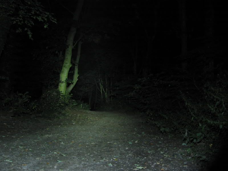 [/IMG]
1.5 amps, is that allowed !
-
Troutie are these a newer breed XPG?
You are right, it does generally just go out of regulation but there is more to it than that.
For starters, the Vf of an LED is not a constant. XPGs are good but variation between LEDs and over temperature and input current can mean the Vf per LED can rise to 3.5V or more which means up to 14V with 4 in series.
I've spent ages trying to make the following bit clear with some technical stuff but I can't...
When the battery voltage is low, the chip gets hotter than when it is high. This can shorten the life of the chip or even cause it to melt and go up in flames. (Well, maybe not that drastic but you know what I mean!)