I got my hands on a pair of thermocouples for a couple of quid each. Two PCU heatsinks for £10 and a couple of 1.5v motors for £3 each. Two rotor blades for £3.
At least, the blade goes round, seems to be enough to keep sufficient heat differential across the thermocouple but it doesnt really feel like its moving much air around so I’ll have a go at fabricating my own impeller sometime.
This is the second version, the first using the metal brackets and one heatsink just wouldnt transfer enough heat to the termocouple.
Ian – i tried it briefly (with an ice cube on the top 😉 ) but the fly leads are too close to the stove to leave there like that without running the risk of damaging them.
organic, read the original thread, linked in the first post.
Funky dunc – naff all! So I will try to make a better blade for it.
I would be tempted to get a solid Aluminium block for the hot side. You will be losing a lot of the temperature differential from the Heatsink doing what it was designed to do.
Get a larger diameter airscrew. shifts more air more efficiently. Or a higherKV motor(more RPM/V)less good for this IMHO.
Saying that, as you increase the load on the motor it will try to draw more current. I doubt the supply is enough to burn out the motor but there will be an optimum point.
I doubt Ill be able to find a more appropriate motor – its hard enough to find one that works at these voltages anyway.
What characteristics would a bigger air pushing screw have? If I want to make my own – i.e. what kind of ratio of surface area to void area? what kind of diameter and what kind of pitch on the blade face?
However, they are usually quoted as having 2 vital statistics. The Diameter and the pitch. Diameter is self explanatory. pitch being how far would it travel forward given one full rotation assuming no losses.
Model aeroplane sites might be a good place to ask.
Looks like they have ones that are thin to be use at high rpm. and these for lower rpm. What constitutes low/high I do not know but would guess you want this sort of thing.
Pick your diameter so as to have no cooling on the hot side and at 70p each you can get a few different pitch combinations for some trial and error.
You want to maximise heat conduction in the base (i.e. thin solid block of copper/alu, or take your existing one and wrap it in tinfoil, bottom half only of course) and maximise power dissipation in the top to maximise your delta T across the thermoelectric module (Which is actually a whole heap of thermocouples).
You want a motor/blade combination that provides an electrical resistance of approximately equal to the electrical resistance of the thermoelectric module, this will give you approximately peak power output from the device.
You want a motor/blade combination that provides an electrical resistance of approximately equal to the electrical resistance of the thermoelectric module, this will give you approximately peak power output from the device.
I’ll never be able to work that out 🙁
I was going to wrap the bottom in aluminium tape to help.
Quite remarkably the thing has kept on running all day long so at least Im getting sufficient delta T (i.e. the top block isnt heating up too much) to keep 1.5v+ output.
Looking at the pics. I would have thought lowering the motor height would get more airflow over the cold side heat sink. That would be my first port of call.
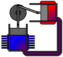
Id love to make my own sterling engine but there’s no way I could machine the cylinder and piston to tight enough tolerances, so I will probably have to get a kit.
Posted 13 years ago
Viewing 31 posts - 1 through 31 (of 31 total)
The topic ‘Ha ha! It only bloody works!’ is closed to new replies.