It's actually mid 60s - but room is identical, with the same stair erm feature.
Can I be cheeky and ask if you've got any photos of how you put it together?
I have lots on my phone. I'll dig them out - maybe tomorrow.
Basically it's 2 drawer units screwed together and screwed to a top rim around the bed (fixed to wall). Then ply facing to everything. But the pics wil be self-explanatory.
Edit: We made the drawers from scratch to max out the available space (and get full extension runners), but we did seriously consider just using 2 sets of 60x60x60 ikea units.
http://www.ikea.com/gb/en/products/kitchen-products/kitchen-cabinets/metod-f%C3%B6rvara-base-cab-4-frnts-4-drawers-black-h%C3%A4ggeby-white-spr-09025138/
Mine are no where near as good as most stuff on here, so many talented people.
Had some left over scaffold boards and decided to be a little creative. Found some old pub sign cigarette cards online and some cast iron bottle openers.
To be mounted on the wall, but you can turn them over to see the information about the pub or sign etc. Some great ones about Royal Naval ships and found a pub sign called 'the Escape'. I paired that up with a cast iron RAF opener. The two below are the most recent ones I have completed.
[IMG]  [/IMG]
[IMG]  [/IMG]
Thanks for the info Alex, no rush on photos of course...may be sometime before I get round to doing it.
Cheers
I made a bike for my daughter 🙂
Lugs and stays are CNC machined from billet, single-sided swingarm, Hope mono mini rear brake with stealth routing..
[img] 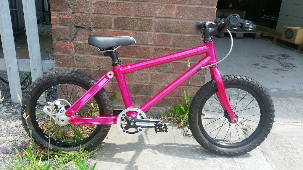 [/img]
[img] 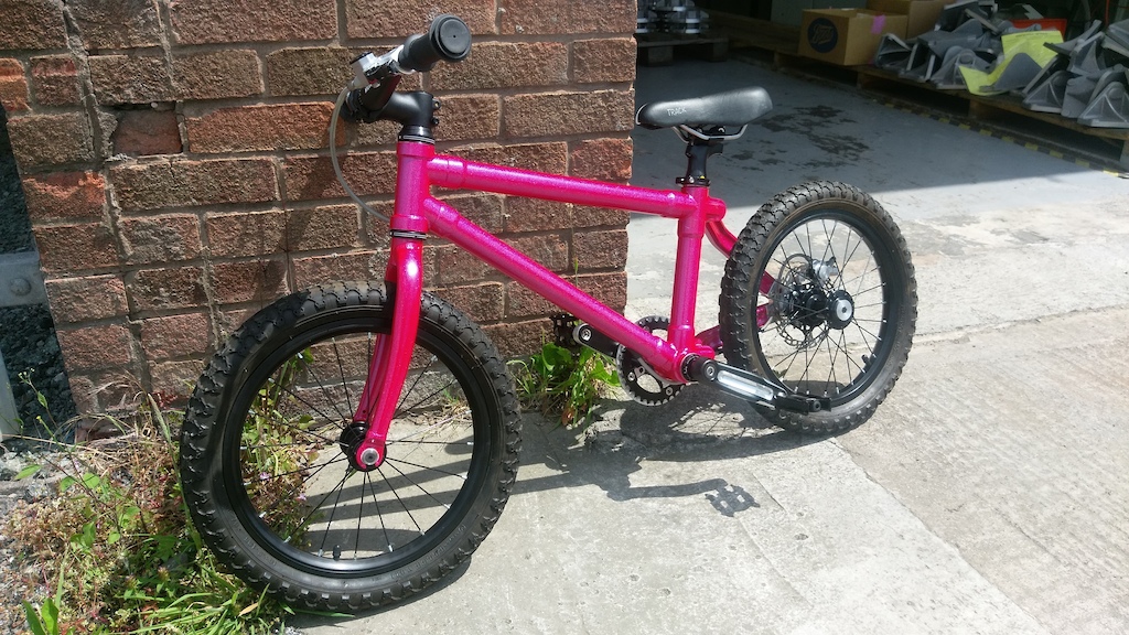 [/img]
As if we weren't following the thread already stevied 🙂
Looks amazing
(better raw, but then I'm not the target market :))
Table and speakers all my own work but I take no credit for the horse and wraith.
[img][url= https://s24.postimg.org/qtcay5lad/GOPR1605.jp g" target="_blank">
Making your own speakers must be immensely satisfying 66deg. Nice work!
I did all the cabinet construction following a design by Joe D'apolito and all the components were in a kit bought from Intertechnik who also offer a crossover build service so I can't really take credit for that bit either.
Never the less my next speaker project has no option on the crossover so ill be having a go at it myself.
I built a couple of percent of this:
Stevie, as impressive as that bike is I hate to say it - it won't hold. Rear fails basic test for structural stability.
m?2j-3
where m is members (you have four - the frame, seatstay, chainstay and dropout tab) and j is joints (you have four where each member is pinned together). If m is greater or equal then it's stable otherwise it's just a flappy box. Unless those are solid joints (as in, literally something solid preventing rotation) then the dropout bracket is going to pivot the first time that goes down a kerb.
If you want to stabilise it you either need to introduce another member or decrease the number of joints.
I sort of get the impression he knows what he's doing...
I get the impression he knows his way around a cad machine, beyond that I don't know. That's why I only assume the joints aren't restrained as that's how it appears. What I do know is stability as it was a massive part the structural integrity course I'm now basing my final uni project on.
But if my word isn't enough, batter in...
http://www.engineeringwiki.org/wiki/Truss_Stability
Ah, an Engineering student, it makes sense now. 💡
?
squirrelking - this is not Stevied's first time making a bike.
Do you think the Lotus 108 suffers the same problem then?
Do you think the Lotus 108 suffers the same problem then?
You maybe haven't grasped the problem SQ's describing. He's describing the axel being able to move if the four bolted connections are able to swivel, not the instance of having a single sided rear triangle. But if non of those connections can rotate then theres not a problem.
Thank you, yes that is exactly the nature of the problem I'm describing.
Ah, so you've assumed that each end of the chainstays and seatstays is a pivot? Why?
I made a minus 8mm head for a Reverb as the GF has a 125mm drop post that is slightly too tall. Think I might still need to take a wee bit off the seattube but it should do the job.
[img]  [/img]
Also made some coat hooks for the hallway out of MX5 parts:
[img]  [/img]
@GeForce Junky, that's a marketable item right there, lots of people would like a little help getting long Reverbs into their frames, or have bought one that won't fit.
Because depending on the way the two surfaces interact that's exactly what they are, given a great enough force to overcome any friction.
If it is two flat surfaces then its a pivot. If they are connected in a way that physically prevents twisting, they are not.
Easy proof - look at a 4 bar linkage (fsr/lawill/Macpherson strut) and try to think of a reason why it wouldn't still allow movement with seized bearings given a great enough force. There isn't one, its just the force required to move it is going to be greater than with good bearings.
Drew up some vintage kyosho parts and got them 3D printed.
[URL= http://i395.photobucket.com/albums/pp36/londonladliam/IMG_0261.jp g" target="_blank"> http://i395.photobucket.com/albums/pp36/londonladliam/IMG_0261.jp g"/> [/IMG][/URL]
Squirrel +1, although I hope that the frame does indeed hold up, what a great thing to make for your child. Good on you steveid.
squirrelking - MemberIf it is two flat surfaces then its a pivot. If they are connected in a way that physically prevents twisting, they are not.
And you've chosen to believe based on no evidence that it must be the former.
+1@GeForce Junky, that's a marketable item right there, lots of people would like a little help getting long Reverbs into their frames, or have bought one that won't fit.
Two points on that brilliant kids bike:
I've held that back end, because I built that wheel - that's a very solid joint at the BB.
It's effectively a triangle. Yes, there are two joints at the rear dropout, but they're so close together that they'll effectively act as one - and actually even if they were all loose then it wouldn't move much as the action of moving the rear section upwards also rotates the axle downwards - it cancels out. Try making a model if you don't believe me.
And you've chosen to believe based on no evidence that it must be the former.
Or rather I've chosen to present a very basic and fundamental potential engineering flaw based on face value. I did this for the benefit of the OP who may or may not have addressed the issue in his design. In return I've had nothing but uninformed crap thrown back at me by people who don't know what they're talking about. I might 'only' be a student but I am/was a fully qualified marine engineer and have 12 years experience working with mechanical systems so I do feel like I edge it on authority on the matter over a bunch of folk that seemingly cannot understand something that has been explained umpteen times now. I am not trying to be a smartarse here, as I said I saw a fairly glaring problem and was trying to do the guy a favour.
This is exactly the kind of groupthink engineers are taught to fight against, I've seen it first hand and the most famous example was the Challenger boost rocket seals where engineers were ignored by people who thought they knew better. And before you all get on your high horses, no I'm not comparing a child's bike to the Challenger shuttle disaster, just the groupthink.
Ben - either it's a triangle or it's not. In this case it's not, the proximity of the joints makes no difference. The difference in dynamic loading to that of static loading (especially with the loading from single stays) is what concerns me though, it's all good now but after a bit of use where will it be? I do however concede that you know your onions when it comes to bikes and it's hardly Fatty McFats touring bike, with proper care and attention there shouldn't be a problem but with correct design there wouldn't be one in the first place.
As I said in my first post it is impressive, it's a very lovely piece of work and I'd be proud of it.
Anyway, I've said enough on the matter, it's really nobody's business but the OP (and anyone who may have seen it in the flesh) so I'm done with the sniping. I've made my case and justified it far more than I should really have to so I'm done.
Fatty McFats touring bike,
That's another thread.
I'm sure the OP took it in the spirit it was intended.
london_lad_liam show us more. What are you building up?
@GeForce Junky, that's a marketable item right there, lots of people would like a little help getting long Reverbs into their frames, or have bought one that won't fit.
Wasn't there a thread in the last day or so with someone looking for a low stack saddle and considering other options such as shorter cranks and thicker pedals to overcome just this problem?
I suspect at commercial rates it'd cost more than a Reverb
GeForce Junky - impressive!
Just a slight warning (that might not be important), but saddles can sag quite a bit in the middle. It shouldn't make it uncomfortable, but it might not feel quite the same when sat on.
I found this out because the original Maverick Speedball had a post up there that even my low weight used to activate the dropper!
I ended up finding a lower profile bolt.
(internet pic)
[img]  [/img]
For jimfrandisco who requested some 'making of' images:
First we made 2 drawer units to fit some ebay 700mm full extension runners. We used pocket holes front and rear so they are all hidden. Routed a groove on all the sides for the drawer bottom (6mm ply).
[img]  [/img]
Then added the frame on top of them around the room to take the ikea bed slats
[img]  [/img]
Added a partition for the triangular cupboard section.
[img]  [/img]
Then placed all the fronts on after measuring 3 times cutting once. All from the same sheet of ply.
Used spacers to get it all right. Everything fitted first time which was a relief.
[img]  [/img]
I don't have any pics, but we fixed the handles to the drawer fronts first with recessed bolts, then drilled oversize holes into the drawers, so that when we used pan-head screws and washers there would bee a couple of mm adjustment available.
We started bottom-right with all but one drawer removed and screwed each drawer front on from behind using spacers and clamps.
Worked our way up the first set then the second.
Very slow work, but our care paid off!
Cupboard is fixed using kitchen cupboard hinges, so we needed to drill 35mm blind holes into it, but I already had the correct bit from the bathroom cupboard project.
@arching london_lad_liam show us more. What are you building up?
So the first two green bits are from a Kyosho Lazer ZXR
Drew the from arm over the last bank holiday…I was bored and find it quite therapeutic (there also quite hard to get hold of if they do break)
The knuckle bit as also for the same car, I have modified so that an m3 nut sits in the bottom (instead of screwing directly in to the plastic) so gives a much stronger front end.
[URL= http://i395.photobucket.com/albums/pp36/londonladliam/IMG_0309.jp g" target="_blank"> http://i395.photobucket.com/albums/pp36/londonladliam/IMG_0309.jp g"/> [/IMG][/URL]
[URL= http://i395.photobucket.com/albums/pp36/londonladliam/IMG_0311.jp g" target="_blank"> http://i395.photobucket.com/albums/pp36/londonladliam/IMG_0311.jp g"/> [/IMG][/URL]
My other project was a Losi xxx CR2 (which had been converted to mid motor) but the old gearbox sad very high so I designed a printed a lower version.
[URL= http://i395.photobucket.com/albums/pp36/londonladliam/20161116_201400.jp g" target="_blank"> http://i395.photobucket.com/albums/pp36/londonladliam/20161116_201400.jp g"/> [/IMG][/URL]
[URL= http://i395.photobucket.com/albums/pp36/londonladliam/20160927_100922.jp g" target="_blank"> http://i395.photobucket.com/albums/pp36/londonladliam/20160927_100922.jp g"/> [/IMG][/URL]
[URL= http://i395.photobucket.com/albums/pp36/londonladliam/15423669_819891511410_1806739128_n.jp g" target="_blank"> http://i395.photobucket.com/albums/pp36/londonladliam/15423669_819891511410_1806739128_n.jp g"/> [/IMG][/URL]
[URL= http://i395.photobucket.com/albums/pp36/londonladliam/20160927_100937.jp g" target="_blank"> http://i395.photobucket.com/albums/pp36/londonladliam/20160927_100937.jp g"/> [/IMG][/URL]
[URL= http://i395.photobucket.com/albums/pp36/londonladliam/15058666_814886845800_833088978_n.jp g" target="_blank"> http://i395.photobucket.com/albums/pp36/londonladliam/15058666_814886845800_833088978_n.jp g"/> [/IMG][/URL]
The green parts where printed with an SLA printer, The grey gearbox was printed on a SLS printer with a graphite additive and they white gear box was a normal FDM printer.
Started Drawing bits to mainly expand my knowledge on 3d printing and 3d Cad to some degree.With 3d printing there is SO many filaments that you can choose to vary how your end product comes out.
Want next try the aluminium 3d printer but thats mega bucks 🙁
squirrelking - MemberOr rather I've chosen to present a very basic and fundamental potential engineering flaw based on face value. I did this for the benefit of the OP who may or may not have addressed the issue in his design. In return I've had nothing but uninformed crap thrown back at me by people who don't know what they're talking about. I might 'only' be a student but I am/was a fully qualified marine engineer and have 12 years experience working with mechanical systems so I do feel like I edge it on authority on the matter over a bunch of folk that seemingly cannot understand something that has been explained umpteen times now.
You are completely missing the point. The engineering facts which you've thrown around are all correct, and in fact obvious- nobody is "not understanding them". The issue is that your sound engineering is all building on an assumption not a fact. And you even said so:
squirrelking - MemberThat's why I only assume the joints aren't restrained as that's how it appears
Maybe the confusion because it was described as a swingarm?
I have zero engineering experience but it looks sound to me 😉 triangle bolted at all corners will be fine I would have thought?
Edit lovely thing by the way!
Can I suggest that any further discussion of stevied's bike should go in the main thread here: http://singletrackworld.com/forum/topic/how-hard-is-it-to-make-a-kids-bike
This is better as a fairly quick-fire inspirational thread of project pics
Smartphone holder bodged together from bits of scrap oak. Hoping it'll make navigation a bit easier on my upcoming touring holiday. Also hoping it doesn't break and ruin my phone...
[img]  [/img]
[img]  [/img]
^ Steampunk iPhone holder. I like 🙂
[b]I know there are some knife guys on here. I wanted to make my dad a knife for his 60th, I started about 6 months out so I had plenty of time, but for various reasons he's 63 next month and I put the first couple of coats of oil on the handle today.
It's the first time I've had a go, and I'm pretty happy how it's turned off out. I bought the Damascus blade from somewhere in the US. The scales are mallee. I let the pins get a bit hot when sanding and it has burnt the surrounding wood, but other than that it's all good.
[IMG] 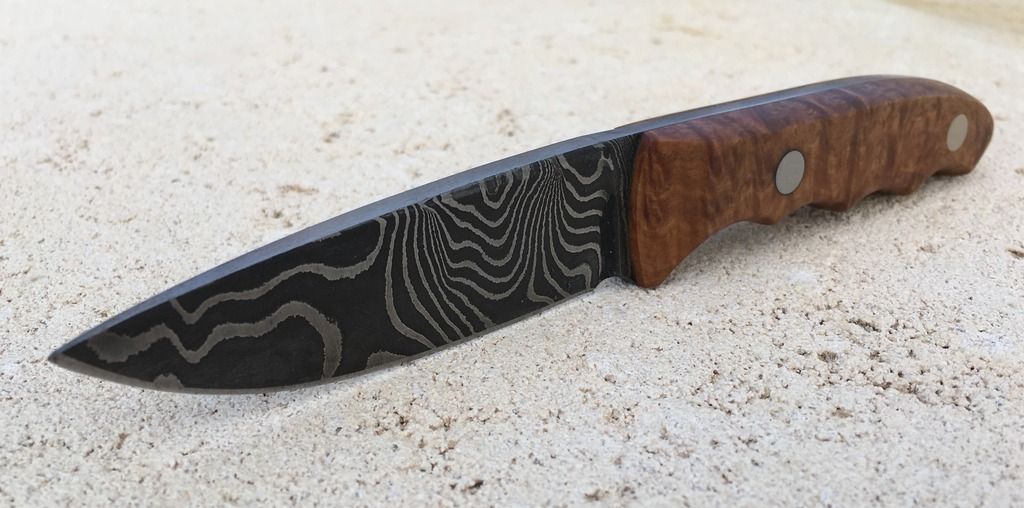 [/IMG]
[img] 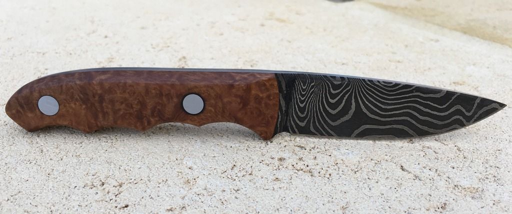 [/img]
[img] 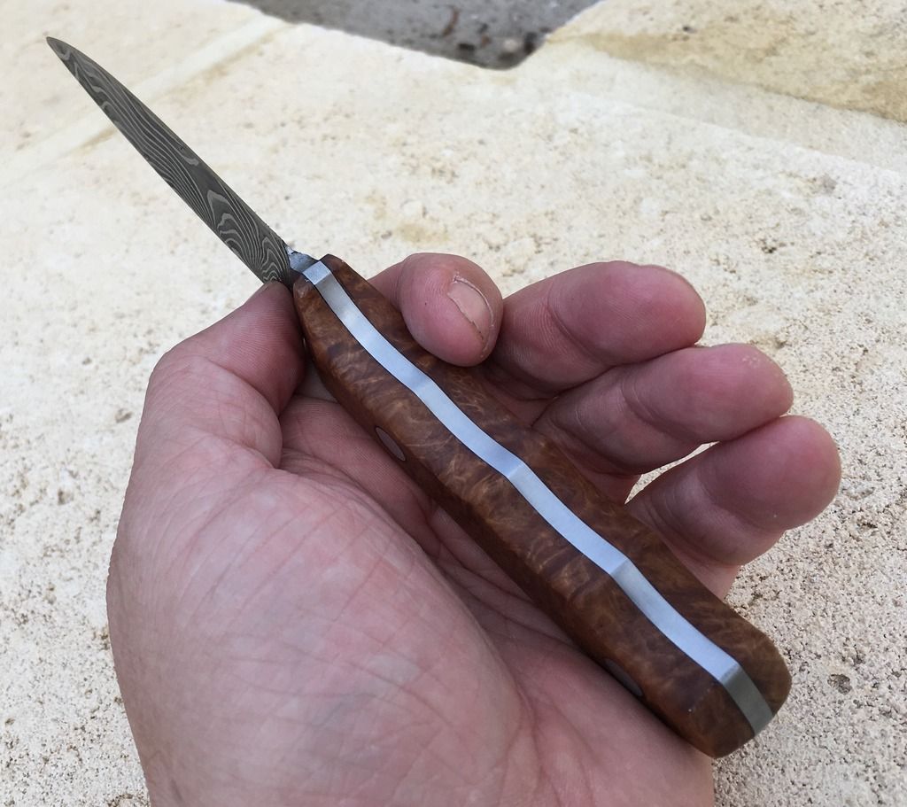 [/img]
[img] 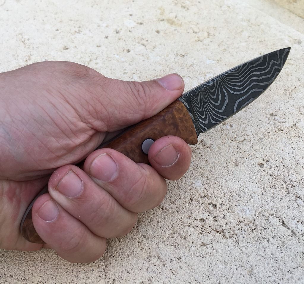 [/img]
Oooooh! That's nice.
Latest project complete.
An adjustable shelf system for eldest son's room.
As usual made from my huge stock of 15mm birch ply offcuts.
Note for future reference 25mm dowel is definitely not 25mm ...or round.
[img]  ?oh=9f237f6786d01799cfae49e926630205&oe=59DD706D[/img]
[img]  ?oh=dbfaacf5b46bc2a908ee5ba347b331ea&oe=59C7B3C7[/img]
[img]  ?oh=c84f8481475a6bb1ffc037bc14085f25&oe=59D968DE[/img]
[img]  ?oh=8357ec230bff2e9bb32cc8eea2180a5f&oe=59E672F8[/img]
[img]  ?oh=2be4f99c63282e7d93f26142a58abf99&oe=5A110FD2[/img]
In my usual style, the requirement for drilling 72 vertical holes justified the purchase of a new tool...
[img]  ?oh=e33424a5d574fa98d1dd478963a96ec0&oe=59DAE989[/img]
finished latest knife just before holiday, there for a holiday picture of said knife
Sycamore with a carbon rod as pin
[url= https://c1.staticflickr.com/5/4276/34424755714_e5c0c51d8b_k.jp g" target="_blank">https://c1.staticflickr.com/5/4276/34424755714_e5c0c51d8b_k.jp g"/> [/img][/url][url= https://flic.kr/p/UrZSwW ]5J4A9244[/url] by [url= https://www.flickr.com/photos/83246699@N00/ ]msh_sco[/url], on Flickr
@ Ishouldbeworking, very nice wood and handle.
[img]  ?oh=8b5cd7c74d102933f79ee0ab1145edca&oe=59D5BE7F[/img]
Just a little something I've been working on. A new box for my RM20 combo, now a head.
Had to learn a lot of new skills but I'm pleased with how its come it. Been going to a community high school wood working class.
Just need to oil, stain or wax the wood and find a nice handle for it and rock the f*&k out.