
[img] 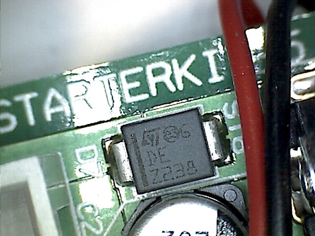 [/img]
I know its a schottky diode, but can't fathom out a serial number, the "Z238" doesn't take me anywhere. I need to buy a few of them as one on a board I'm using has blown.
It's Brian.
Beyond me, I'd have said it was a voltage regulator. Never heard of a shottky diode.
Z2xx are usually zener diodes but not aware of a Z238
It's Hal, he fell on hard times after Space Odyssey. Spent a few years as a bit part actor for TV, most notably playing Orac in Blakes 7, but he's ended up in a dead end job on a circuit board.
Shame, he had potential.
It's a flux capacitor.
I would have guessed that the Z may be for Zener but if you know it is a schottky then that is that theory blown out the water.
It's an interrociter!
Miss Jones?
According to the PCB he's called D7.
Turbo Encapsulator ?
If it is indeed a Schottky diode, then it's one made by ST so take a look here:
http://www.st.com/web/en/catalog/sense_power/FM64/CL1571/SC541
I don't recognise the component, but am wondering whether the board is an important part of the Starship Enterpirse?
ST is the manufacturer,
E3 I think means a lead-free package,
Z238 is I suspect the production location and date.
so the 6 D and E could well be the thing that indicates what it is.
I could be completely wrong, it's been about 25 years since I designed electronic things!
I nominate Ted. Ted the component.
Try this -
[url= http://www.st.com/web/catalog/sense_power/FM114/CL1460/SC234/PF64210 ]http://www.st.com/web/catalog/sense_power/FM114/CL1460/SC234/PF64210[/url]
Cheers,
Rio's link works. Found it at Farnell too, a whopping 14p each.
Continuum transfunctioner
It does look like a device whose mystery is only exceeded by its power
Can't be a quality component, they can't even spell "Star Trek" properly on the board.
Can't be a quality component, they can't even spell "Star Trek" properly on the board.
Star Terki, ready for xmas.
Daft question but if you dont know what it is, how do you know its not working???. 😯
A multimeter will tell you which bit of the board isn't working as expected
You have me there.... if you don't know what the component is and what it does then how do you know its not working as expected?.. what kind of multimeter do you have? must be pretty fancy!! 😀
Well, he knows it's a diode, so he could do a basic test mith a meter to check for conductance (couldn't he?)
That's Steven, Steven Schottky.......
PS. Make sure you put the new one in the right way around. (The black "stripe" down the left hand side of the top of the package indicates the cathode generally)
You can easily work out the voltage rating as follows:
1) Look at the rating of the capacitor that it sits next too, it's breakdown voltage must be less than this!
2) Measure the rail voltage across one on a "working" pcb, the breakdown voltage will be just a little above that value
3) Unsolder a good one, use a bench powersupply in constant current mode to find the breakdown voltage
I suspect, this device is acting as the supply rail protection device, and was killed by a reverse polarity supply (the most common cause of dead electronic do-dahs!) I imagine the "dead" one is obvious because it's toast!
I think you are missing my point, he didn't know what the component was but had concluded that it had failed I'm just curious as to how he knew it had failed. Admittedly being a diode is easy to test with most meters however on board testing is notoriously difficult to without the correct test jig to mimic working conditions and i would never test a component on board as its not isolated from other components as you could possibly bugger up another component. Its smt so is easy enough to remove and test but each to their own 😀