I bought a jump frame to do this to an old Jamis HT I have lying around (thanks for the idea taki):
[url= http://farm5.static.flickr.com/4023/4641090341_94c3987844_z.jp g" target="_blank">
[url= http://www.flickr.com/photos/takisawa2/4641090341/ ]21032010287[/url] by [url= http://www.flickr.com/people/takisawa2/ ]pten2106[/url], on Flickr
I aim to "build" the utility bike as above, and bolt/CF glue a humoungous rack on it (thinking old bar roof rack sawn in 2?)
My Q is how best to attach the top-tube of the rear bike to the seat post of the front. My suggestions are:
1. Drill the top tube (difficult to do accurately) and leave metal in front of the hole, possibly add a slot at the back and a bolt/nut to tighten.
2. Drill it and cut away the front (easier to get an accurate shape), leaving a bit on each side and a hole through which a jubilee clip could go to secure it.
3. Erm I had thought of 3 but I've forgotten.
Any suggestions?
[url= http://farm3.static.flickr.com/2536/5735823331_8228a984c0_z.jp g" target="_blank">
[url=  [/url] by [url= http://www.flickr.com/people/7693620@N05/ ]alan cole[/url], on Flickr
[img]  [/img]
Cant you just glue it?!! 😀
I want it to be remove-al-able...though I did think of a CF reinforced clamp, I reckoned it might encourage the thread to co off-topic, and I am genuinely looking for ideas.
Something like this:
[img]  [/img]
eg [url= http://uk.rs-online.com/web/search/searchBrowseAction.html?method=browseSuperSection&N=4294962138#Steel%20Tube%20and%20Aluminium%20Structural ]http://uk.rs-online.com/web/search/searchBrowseAction.html?method=browseSuperSection&N=4294962138#Steel%20Tube%20and%20Aluminium%20Structural[/url]
leave the top tube long. drill hole for the seat post. clamp both top tubes together. with jubilee clamps or similar.
I'm not an engineer but how about modding the frame with some sort of a clamp from a kids trailer bike OR modding a clamp from a seatpost rack.
[img] http://bike-bags.com/wp-content/uploads/2010/04/130.jp g" target="_blank"> http://bike-bags.com/wp-content/uploads/2010/04/130.jp g"/> [/img]
But it is not enough of a niche bodge to be considered, however always an option.
Was thinking a Fork/steerer star nut type thing, but it won't help with lateral stability.
(nips off to put kettle on)
Miezsko - this is LOOOOOOOOOW budget!
nick - ta but sorry, top tube is square!
thom - sounds good, I reckon drilling it accurately enough would be difficult to impossible with the equipment I have though.
carlos - ? Lateral stabilty will come from the BB of the rear frame being bolted into the dropouts of the front frame, so it's not a big issue I don't think.
Something like this knocked up by your local machine shop?
[url= http://farm6.static.flickr.com/5143/5735847913_2a25b0afa1.jp g" target="_blank">
[url= http://www.flickr.com/photos/35894025@N02/5735847913/ ]clamp[/url] by [url= http://www.flickr.com/people/35894025@N02/ ]robbo1234biking[/url], on Flickr
nick - ta but sorry, top tube is square!
Then use a square one and make a bush for the seatpost (bit of wood/plastic with a hole drilled in it)
[img]  [/img]
[img] 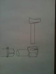 [/img]
Hmmm, I may even know of a machine shop 😉
Modified for square!
[url= http://farm3.static.flickr.com/2743/5735860665_af0aee2615.jp g" target="_blank">
[url= http://www.flickr.com/photos/35894025@N02/5735860665/ ]clamp[/url] by [url= http://www.flickr.com/people/35894025@N02/ ]robbo1234biking[/url], on Flickr
Nice but I think I'd prefer to save any machine shop favours for non-shite projects!
The top tube will collapse if you try to clamp it unless you fully support it or put an insert in it, so something like has been drawn above is the way to go.
It's a 7lb 13" jump bike, I expect the topp tube to be fairly thick!
Option 2 or something similar winning for me despite lack of support!
Don't stop there Al, bolt on a third bike! 🙂
Macmerry is the way to go 😉something like has been drawn above is the way to go.
I dont think youll get enough clamp load like that. THe hoseclip is trying to do two things and will end up loosening and sliding up and down the seatpost.
It's a 7lb 13" jump bike, I expect the topp tube to be fairly thick!
Yes but the wall thickness isn't enough on it's own. It's strong because it's a tube. (strong meaning stiff, robust and able to withstand wear.)
But the top tube is pressing against the seatpost from behind, what other loads are there to accommodate?
EDIT - I know rich, but it would just be resisting tearing forces from the jubilee clip?
PaulGillespie - Member
Don't stop there Al, bolt on a third bike!
A real bike centipede 😉
Al if it's really LOOOOOOW budget than a piece of string is enough! what's the worst that can happen?
[STW expert mode]
For me option 1 looks stronger then option 2 and because I'm studying accountancy and have no idea about engineering it must be.
[STW expert mode]
The lateral movement of you pedaling?
It's drilling thro' the tube to fix the jubilee clip that concerns me. Any movement will cause the screw to wear away metal so before too long it will be a large oval shaped hole, just before it fails.
Edit. OK, I see the whole Jubilee clip passes thro, the tube, but the same applies.
[url=  ]Holy ......[/url]
I'd also be worried about the rear dropouts on the GT. You're asking them to take a load they were never designed for.
How about something like a USE seatpost
Put a bar with a couple of holes in it through the top tube
[img]  [/img]
Then put a u bolt around the seatpost
[img]  [/img]
Stronger than a jubilee and much stiffer
Any decent flapjack recipe, and bake it on.
I'm trying to work out if I'd prefer to sit at the front or the back... 😯
I'd also be worried about the rear dropouts on the GT. You're asking them to take a load they were never designed for.
+1
It's the joint between the dropouts and the bottom bracket that I would be worried about, can't really see how you could make that strong enough, either vertically or laterally.
Brilliant idea though and make sure you get a video of the first ride.
I wouldn't pi$$ about with connectors, they'll probably shear unless you make them really chunky. I'd lash something up out of thick ally tube and/or channel picking up the two top tubes. Rotate the back bike clockwise a bit to line the top tubes up and then bodge away.
Now you've completed your POC rear disc brake mount, can we expect to see another black scab/cutlery combo on this bike? 🙂
one of these;
[img]  [/img]
[url= http://www.winstanleysbikes.co.uk/product/39107/Adventure_Pre_2011_Trailer_Bike_Hitch ]http://www.winstanleysbikes.co.uk/product/39107/Adventure_Pre_2011_Trailer_Bike_Hitch[/url]
with a solid 6" rod of solid metal inside the cut off top tube to spread the load where the pin goes through.
I like it, but it lacks ambition. 😉
[img]  [/img]
You know, I do enjoy your postings, Al.
It's the heady combination of being quite possibly the cheapest man in Scotland coupled with a wonderful attitude that ensures you never let common sense and experience get in the way of a bad decision!
Chapeau! 😀
I stil don't see that the upper junction is under significant stress -the only force is pushing it together.
I hadn't calcualted the forces on the dropouts (what would they do anyway?) but here goes (Using 16" chainstays and a 24" front centre):
Dropouts....designed to take the vertical load of 3/5 of a rider's bodyweight, say 100kg, i.e. 60kg - off road?
With the new weight distribution, I calculate with my 80kg, the force on the rear hub will be, 3/7 of that i.e. 36kg (+shopping etc). The force on the front dropouts i.e. dropouts will be ~72kg? Road use only? Seems OK to me.
WW not sure what you mean, no need for a pivot there.
Still thinking it'll twist some under pedaling and the drop outs are designed for stuff to ..err drop out of, where as a wheel will be pushing upwards into them so that coulkd be an issue.
Cut the top tube & down tube keeping the steerer attatched and re-weld it back on allbeit a shorter inverted one that the seatpost will then simply fit through. To clamp it cut a vertical line top to bottom of the steerer and clamp with jubilies.
carlos, draw it out and think it through rather than guess!
And I cannot weld.
al - not for the pivot, more a convenient way to get a bracket that would fit a seat post easily.
Not a guess Al, if the inverted top tube/steerer is welded on at the same angle (it could be welded at pretty much any angle)as the seat tube I don't see why it won't work. Obviously the down tube would be trimmed right back to the steerer tube.
Maybe I'm just $h1t at explaining things, can't do pic's as no facilities at work.
Meh, but if you can't weld
Ah I see WW.
Missed this gem:
Now you've completed your POC rear disc brake mount, can we expect to see another black scab/cutlery combo on this bike?
It's getting re done. I suspect there may well be some carbon attaching the rack to the bike for you to flame.
Oh hang on, the disc mount on my forks is still working fine 🙄
EDIT carlos, this is where you are guessing:
Still thinking it'll twist some under pedaling and the drop outs are designed for stuff to ..err drop out of, where as a wheel will be pushing upwards into them so that coulkd be an issue.
Your solution also attempts to clamp a 30mm ID tube, supported on 1/3 of it's surface by the top and down tubes, around a 27.2 tube - I presume you are thinking of a shim?
The rear dropouts might be OK but just imagine that the seatstays and chainstays of the rear frame are several metres longer to understand the leverage they are exerting at the dropouts. It isn't the dead weight that's the issue, it's the leverage that's roughly doubling the load. Also a wheel would be pushing upwards but this will be pushing about 45° backwards. I'm not saying they'll fail as they are, just that I'd be more concerned about this than connecting the top tube. Depends hugely on your weight, the loads you are carrying and the bumpiness of the terrain though.
I'm not flaming you CA, I'm joking. You are sensitive about your lovely creations aren't you? 🙂
Iain have a look at my calcs - if they are wrong pease let me know.
boblo, I'm doing stuff that no one else is and it's working, it just gets a bit tedious to get flamed for that alone, I don't flame folk when they are being constructive.
ever ridden a tandem - that joint is under twist
Tandems not nearly as stiff, more weight (which is pedalling) on the back too.
Reinforce it sideways. Otherwise it'll fold at the dropout.