Having read other posts it seems you guys know a thing or two about home LEDs. I have a problem -
I've built a x7 XPG R5 lamp using a maxFlex5 driver having cut my teeth on a x3 XPG Lumi can conversion.
Pic of the x7 unit.
[img]  [/img]
I was expecting it to blow the Lumi can away with over 2400 lumens but it hasn't worked out as planned. Pic 1 below is the x3 Lumi can, Pic 2 is the x7.
Pic 1
[img]  [/img]
Pic 2
[img]  [/img]
I've had some feedback from George at TaskLED and it looks like the total Vf is exceeding the maxFlex limit of 23.5V and clipping the output current and hence limiting the light output. I'm not sure why it's doing this as the datasheet values for individual Vfs at 1000mA is 3.3V, therefore total Vf should be 23.1V, under the driver limit???
Anyhow, the question is, can I do anything about it? Can I affect the total Vf and hence get the full 1000mA through the LEDs?
Cheers
Stuart
My guess - the datasheet shows "typical" values, if your xpgs are drawing 3.4V each, then you're knacked!
I think i've seen 3.7volts mentioned somewhere. 3.3 might be a average.
not sure if the 3.7 was for XPE's though.
You could try taking one of the LED's out of the chain and that would prove whether the regulator is running out of volts or not . . . 6 XP-G will definately be within the operating range . . . not sure if that is possible with the board you have or not . . . I have to say that it's almost certainly on the limit . . . you could also set the driver output to, say, 750mA as the forward voltage reduces with reduced forward current . . . 7 XP-G's at 750mA will still blow away 3 at 1000mA . . . plenty things to try . . . of course you could just lob a voltmeter over the LED chain and see what the forward voltage actually is 😉
Fd
Edited to say the datasheet suggests you should be OK . . . have you configured the driver to run at 1000mA ?
there must be something amiss there cos I am runing the same config
7 xpg from a maxflex 5 [IMG]  [/IMG]
at full whack from a 14.8 volt LiIon pack and it looks like this
[IMG]  [/IMG]
what battery are you using .
have you configured the maxflex because even at the default 350 ma it should look like this
[IMG]  [/IMG]
Bloody hell Chris, thats like daylight!!!
You need more head room on the 23.1 volts.
I would lose a lED if I was you (centre)
Also your beam pattern looks poor what lens are you using?
But you are on the right track keep going
The LEDs are on a MCPCB so taking one out might be difficult.
I've metered the total Vf in various settings and I have to run it in 700mA to keep the Level 5 multimode value below the 23.5V limit. This means max theoretical output is only 1700 lumens, which is bit poor.
trout - I've tried all the settings from 350mA upto 1200mA and the max output seems to be pretty much the same. I'm not getting anything like the pictures you posted.
we need more details here
you have not said what battery you are useing .
have you heatsinked your maxflex .
I fear you have damaged the maxflex in some way
I have 4 of these built and running fine does draw nearly 2 amps from the battery on full so you do need a good powersupply .
sorry
Hi Trout
It's the same battery as you are using, a 14.4V Li-ion. The maxFlex is bonded (with Artic epoxy heat transfer paste) to a 8mm think Ali plate inside the housing which is an interferrence fit in the can.
It seems to working in all other respects ie menu selection flashes etc.
George reckons I've just got a MCPCB with particularly high value Vf LEDs on it.
Don't suppose you've got a spare maxFlex and MCPCB I could buy??
I have just soldered up my last maxflex today but do have quite a few on there way from George so you are welcome to buy one of those when they arrive .probably wed thurs
one way to see would be to short round one of your leds on the board .
does`nt matter which one just scrape the coating off one of the traces each side of the led and carefully solder in a bridge .
then you would be down to six leds .
I am nearly sure it is a damaged maxflex .I have had over 600 xpgs and all have been low vfs so I dont think it is the leds .
as if your leds took you over the 24 volts the maxflex would still boost up to its maximum and still light the leds up pretty well .
and it should work at the lower drive currents .
have you checked all the solder joint on the maxflex .
specialy the 2 grounds as they seem to be harder to solder to and I have had a couple of selfbuild kits returned to check and it has been dry solder joints on the grounds .
I've just measured each of the individual Vfs at 700mA:
3.44V, 3.29V, 3.18V, 3.34V, 3.42V, 3.34V, 3.36V, Total Vf = 23.37V
Total Vf measured 23.0V
In theory these should all be around 3.2V
I'll check the solder joints and try again.
Trout
I've bi-passed one of the LEDs (one I've now bust as the little dome has come off) and I'm getting a full 5 levels of brightness in the 1200mA setting, which suggests I'm not hitting the Total Vf limit. It is brighter but still nothing like your image above. This would suggest to me that the maxFlex is ok and that it is the LED board??
I think I'll change them both and start again afresh, so if you've got a spare x7 XPG R5 MCPCB I'd be interested.
Stuart
trout, That is awesome for a home brew 8)
What is the amp hour rating of your battery?
I've found that pulling over 1.6A from a 2.2Ah battery can pull the voltage down & cause probs - ended up using 6.6Ah on my twin HID set up to prevent the control circuit switching to low power.
Poisonspider .
Sorry I have no spare 7 up boards
I know what you mean with the domes as the optic sits very close to them and when removing the optic if it tilts it crushes a couple of the domes .
Snaps has a point how old is your pack it may just be a very tired one
Thanks Rich but I cheated and got a machine shop to make it .
got another 50 on the way if any one wants one to build up .
The battery pack is fine, it's a 4.4Ah Lumi bottle and having monitored the discharge circuit and it puts out the 14.4V for most of it.
Trout
How much for a kit? I might be interested. (especially seeing as I now need new internals for my kit). Email in profile. Thanks.
I've now managed to get this working with a new MCPCB. It must have been a cumulative effect of particularly high individual Vfs on the old board. It looks like the maxFlex is fine.
Consequently it is much brighter (I have a pic but can't upload it for some reason?) but still doesn't look as bright as Trout's above, even at 1200mA and a fully charged battery. I suspect it might be the shitty camera I'm using. I take it you've turned the flash off Trout?
He didnt use a flash and had a 6 second shutter @ f4, If you're using any less it will appear darker to you 8)
Rich
been dry solder joints on the grounds .
Use a flux pen - makes pcb soldering a doddle even smd with your iron
Glad you got it working .
I am curious about your old board though have you spoke to cutters about it .
with the pics I used the standard mtbr camera settings as rich says and it does make the light seem brighter than real life .
yours should be lighting up a whole field if working right now .
Trout
I haven't talked to Cutter about it, I just ordered another board. I haven't measured the voltages on the new one because it's giving me 5 distinct brightness levels at 1000mA (and 1200mA) which it wasn't doing before. Plus of course it is noticably brighter at full tilt so I'm assuming it's working correctly. It may be worth dropping them an email just to give them some feedback though.
With the camera, I'm just using a compact digital, haven't a clue what settings it's on but that explains the difference in the images. It's reaching the end of my garden quite easily which is 150 feet away, although I haven't actually tried it on the bike yet.
I'm now thinking of my next project, a Hope HID can conversion with x5 XPG R5s on a custom heatsink. Have you used the Ledil Lisa2 clip on optics? Are they any good? Also, what's your view using a master/slave pair of bFlexs to drive them? (plan was to use a 14.4v Li-ion battery)
6 seconds at f4 no ****ing wonder they look bright.
Hi Poisonspider
Dont waste your money on the lisa`s I mailed Ledil and had a mail back sayint they are not good for the xpgs if you want a long throw very floody .
Slaving 2 Bflexs seems a waste and makes it a very expensive build .just for the extra led
or split them into a 3 and a 2 and use 2 of tthe Blackcat drivers off ebay .
I've managed to upload the pictures for this now.
First one is a standard snap using auto settings:
[img] 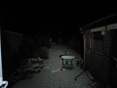 [/img]
This second one is using Trout's settings (6sec, f4 etc)
[img] 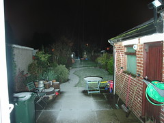 [/img]
Obviously these were taken on different days, the 2400 lumens haven't melted the snow 😉