Forum menu
I need a new suspension link for my Intense as they don't make them any more and can't find one for sale anywhere so I'd like to make my own.
We've got MasterCAM at work and all the CNC kit to do it but I'm not too great on the drawing side of things so was wondering if there might be some kind person on here who may be able to help?
I can draw up the main shape but want to improve the central web to make it stronger. I have an idea of what I want but don't have the necessary skills to draw it...
This is the original link and it's the central web I want to modify:
[img]  [/img]
Without knowing the exact sizes and locations of the areas that mate to other parts, what you are asking is next to impossible. If you knew the sizes modelling it up would be quite easy.
Also with respect to the part you want to improve, are you sure it wont foul other parts of the bike while it rotates?
id be happy to do it but im unavailable for 2 weeks
How urgently do you need it? I could probably model something up and do a drawing for it...but pretty busy at the moment and away at the weekend.
Do you have all the hole centre dims etc? Or would you need them all measuring up? That can be quite hard to get exact, but again I could have a go taking measurements from the original part?
As above, you'll need to take into account clearance and stuff, but presumably that's easy enough to do if you have the rest of the bike to hand.
Would you be machining it from billet and swapping the welded tube joining the two halves for a solid part of the component? I assume this is the part of it you refer to as the central web, rather than the machined pocket on either side?
Thanks for the replies guys. I have the dimensions for the main 'sides' and hole positions, widths etc. Just need some input/design on the web section. It will be made out of a solid billet (same as the original).
I've got the machining skills but not the design skills.
The machined pockets are easy to machine and have them drawn up already. Also have the centre weight reduction hole through the centre web done.
Not in any great rush as the one I have is holding out for now but would like to get it done fairly soon but happy to wait for help 🙂
Sounds like you are almost there? Are you drawing it up in discrete bits or as one component?
Can you not just take the dims of the original web part and add a bit more meat in all dimensions? Sounds a bit crude but it would probably be enough? Perhaps turn the rads at the ends into arcs, if you have adequate clearance?
My e-mail is in my profile if you want to send over what you've got so far and what you were thinking of for the central web.
Although, if anyone else is thinking of getting involved and can turn it around quicker than I can - crack on! The more the merrier.
What bike is it from? Would be good to see a pic of it in situ...
If you have Mastercam, just model up your toolpaths and cut from a block the way you would normally ?
Its not really any different
If you know how you would machine it you are 80% of the way there.
Have you got a CMM or a probe on the cnc ?
as that would help , but its simple enough to measure what you have manually.
Like others have said, Id help but Im stacked out at the moment
I would be a little careful as you do not know what the part material is exactly and the possible teat treatments used.
The part its self would be very simple to reverse engineer though. It looks like it may be 3 parts welded? It may be easier just to machine from solid, however this could change the mechanical properties..... Also those bearing will require a hole fit tolerance, for example H7....
I've got a CMM and have taken the sizes, hole positions etc from the original link I have. From what I've read the Intense linkages are 6061 aluminum which I can buy from our supplier.
There is plenty of clearance on the existing link which is why I'm looking to make the new one slightly stronger/less flexy.
The current one is machined from solid billet and this is what I'll be doing too.
could sort you out Monday if you haven't got it done by then. I'll get one of the apprentices to do it and he can write it up for one of his units. Give the thread a bump on Monday or email me if my addy is in profile. Just make sure your fillet rads are as big as you can make them as that's the weak area on that design.
Like I say above, have you got anything you can mail over and I can look at it when I get a chance next week.
Probably worth sending something over to raveydavey too for one of his apprentices to look at too.
make it in two halves
.. and bolt it up, and make it from 7075. sizes for bearings is easy, look it up on the net.
Surely 1 piece is stronger than two? It's not a problem machining complete from 1 piece..
What's the problem with the link? It looks like the top link off a Tracer which is encapsulated at both ends and the centre bit doesn't [i]really [/i] do anything but keep the 2 halves together/apart. Is your's broken?
Oh and if you've got the measurements I could do it but probably not for a few days and there's a good offer up there already.
Gaz
Oh and
[url= http://www.extrauk.co.uk/product/list/Intense_Parts/Intense_Tracer_2/ ]http://www.extrauk.co.uk/product/list/Intense_Parts/Intense_Tracer_2/[/url]
I machined something similar a few years ago on a manual Bridgeport, none of this modern CNC stuff!
If you still need a CAD model put some dimensions on your photo and I'll do something over lunchtime.
The problem with the current link is that the original owner fitted one of the bearings on the wonk and it has swagged the inside lip meaning that the bearing no longer sits square.
The T2 link is totally different and I've had a few emails with Intense about suitable replacements but they have nothing that will fit.
[img]  [/img]
Here's the link in position:
[URL= http://i729.photobucket.com/albums/ww299/deesta-pics/IMAG35091_zps8f947617.jp g" target="_blank"> http://i729.photobucket.com/albums/ww299/deesta-pics/IMAG35091_zps8f947617.jp g"/> [/IMG][/URL]
stevied - made a start on it, but sent you a couple of questions about the dims between plates and cable routing from your pic above....
JUst had a thought.
If you've been talking to Intense and they don't have any left won't they supply you a CAD model? Worth asking.
Tried that...no joy 🙁
@stumpy:
Emails seem to be not sending for some reason.
In answer to your q's:
The inside ends of the flanges are parallel. There is a slight ramp down on the outer sides from 66.5mm to 60mm. I'm thinking of leaving the outer sides parallel to give a bit more strength.
There are 2 cables that run over the central web but, even with larger rads, this won't cause a problem. I've stopped some cable wear using velcro and cable ties but might look at adding a stainless steel plate on the top, or a couple of cable guides if possible but these could be added after.
Cheers
Steve
stevied - Member
@stumpy:
Emails seem to be not sending for some reason.In answer to your q's:
The inside ends of the flanges are parallel. There is a slight ramp down on the outer sides from 66.5mm to 60mm. I'm thinking of leaving the outer sides parallel to give a bit more strength.
Looking again at the pics at the top of this thread, I think I've answered my own question....
On the first pic you have posted in this thread of the linkage, there is a step down in plate thickness just to the right of the cross member (towards the end that attaches to the frame). This must be where the inner width change is accounted for (43 at one end and 46 at the other).
Dunno why the e-mail is not working.....
The faces at each end (outside and inside) are parallel. The stepdown from 66.5 to 60 (3.25mm per side) is taken, basically over the area where the cutout in the face is.
Think email is something my end 🙁
Stevied - make sure you get 6061-T6 (UTS ~310MPa) from your supplier not just 6061 (UTS ~124MPa). While a 7xxx aluminium alloy will be stronger (~500MPa in the T6 condition), the 6061-T6 is more resistant to corrosion.
Cheers dunsapie. I've been told that 6082 (HE30) is a better/updated version of 6061. I can get some more info from our suppliers to see if it's T6 but, hopefully, it will be as we have lots of it in stock 🙂
We use the aerospace version of 6082-T6 at work, mainly for it's corrosion resistance properties.
Have you considering a chromate conversion coat (alochrome) and anodizing or paint for extra corrosion protection?
Yeah, will be anodised to match the other linkage 😉
6082 is the alloy generally available in Britain in the USA 6061 is readily available its what we used to make bikes out of stateside but not for stressed parts ,it generally proofs at about 300-370 Mpa which is roughly the same as en1 mild steel ( generally the cheapest grade of steel you will find), wtf is the aerospace version of 6082 an aerospace certification process doesn't mean its any stronger just that its falls into a certain range or has no great big anomalies in its structure,
edit but that bit looks like its 10mm thick in places so its no big deal
The stronger grades are 2000 series and 7000 series with the strongest commercially available aluminium alloy available at 700Mpa plus (nearly up there with cromo) and that far exceeds 7075 you also need to start looking at how these materials were processed for example a 50mm bar slice will have significantly better properties(up to 20% increase) than a bar slice at 150mm however 6082 will generally be within 15 Mpa of its proof across the board ,the higher tensile offerings can be as far as 50mpa difference dependant on bar diameter alone and we have had problems when companies supply plate cut to offer the same dimensions as wrought rectangular stock ,this has caused part failures as its been a lower proof value than the design calculations
you may be better with material in T6511 condition just because if your making something you don't want to warp if you do hog the material out of the middle in one great big hit t6511 means its been stress relieved by a bit of stretching and is why we machine our chainrings out of it and they don't warp like a pretzel when they get the middle taken out.
As for is a part weaker in two pieces, not necesarily by the time you have machined through a grain direction because "that was the size of billet it was cut from" you can cause problems , I'm only basing this on experience of designing and specifying parts for Defence and F1 racing where we couldn't forge a component net or obtain forged stock and machining two parts and bolting them made stiffer lighter more expensive pick all three, it is however a good set of rules old school designers consider come into play when they sit down to machine something to with in an inch of its life
what mick said. 6082t6 is our version of 6061. any metal supplier will have 6082t6 (he30) on the shelf in hundreds of different shapes and sizes. they wont have 6061.
and please remember stiffness and strength ARE NOT THE SAME THING!!!
Some of the aerospace 6082-T6 specifications for example are BS L111, BS L115 , BS EN2326. They even say British Standard Aerospace Series on the specification document 😉
These materials have the A,B and S basis strengths quoted in documents such as ESDU MMDH Metallic Materials Data Handbook (formerly DEF STAN 00-932) for the L, LT and ST grain directions for various bar / billet sizes.
The US equivalent is the MMPDS, Metallic Materials Properties Development and Standardization (replacing MIL-HDBK 5).
Wow....some "L" numbers survived when I was at BAE in 2005 I recall them going the same way as calling up "EN" numbers I don't think this was due to standardization but more from the demise of UK manufacturers of materials dying out and us having to adhhere to euro or international suppliers
Managed to make a start on this and have help onboard for the inside profile 🙂
Outside fully machined on both sides (6061 T6):
[URL= http://i729.photobucket.com/albums/ww299/deesta-pics/IMAG36401_zps55306cf1.jp g" target="_blank"> http://i729.photobucket.com/albums/ww299/deesta-pics/IMAG36401_zps55306cf1.jp g"/> [/IMG][/URL]
[URL= http://i729.photobucket.com/albums/ww299/deesta-pics/IMAG36411_zps4a32d1af.jp g" target="_blank"> http://i729.photobucket.com/albums/ww299/deesta-pics/IMAG36411_zps4a32d1af.jp g"/> [/IMG][/URL]
Looking good....
Really must crack on with it...! 😳
Really must crack on with it...!
No rush at all, boss has been out so managed to get a bit more done 🙂
Bit more progress (thanks to stumpy for the CAD work) 😉
[URL= http://i729.photobucket.com/albums/ww299/deesta-pics/IMAG36441_zpsf107b860.jp g" target="_blank"> http://i729.photobucket.com/albums/ww299/deesta-pics/IMAG36441_zpsf107b860.jp g"/> [/IMG][/URL]
Looks like it's coming along nicely!
I meant to say in my earlier e-mail to check the dims! Should be right - but without the usual drawing check process (like I'd do at work)there is always the chance of a mess-up somewhere.
Are you gonna get it anodised?
Doing that bit of out-of-work CAD has got me thinking about resurrecting my custom light can designs that I started ages ago!!
I did check the dims and all ok. Yeah, hoping to get it black anodised to match the rest of the linkages.
Custom light you say? Here's one I made earlier. 7 x XML-2 @ 3a = approx 7500 lupins 😯
Adjustable side pods and an aspheric centre lense for a tight beam.
[URL= http://i729.photobucket.com/albums/ww299/deesta-pics/IMAG0005_zpsffd38f18.jp g" target="_blank"> http://i729.photobucket.com/albums/ww299/deesta-pics/IMAG0005_zpsffd38f18.jp g"/> [/IMG][/URL]
[URL= http://i729.photobucket.com/albums/ww299/deesta-pics/IMAG0006_zpsf7b738e5.jp g" target="_blank"> http://i729.photobucket.com/albums/ww299/deesta-pics/IMAG0006_zpsf7b738e5.jp g"/> [/IMG][/URL]
[URL= http://i729.photobucket.com/albums/ww299/deesta-pics/IMAG0009_zps3fac7f8e.jp g" target="_blank"> http://i729.photobucket.com/albums/ww299/deesta-pics/IMAG0009_zps3fac7f8e.jp g"/> [/IMG][/URL]
This was as far as I got with mine...
[URL= http://i105.photobucket.com/albums/m215/me96kka/LightAssyFrontISO_zps69005fdb.jp g" target="_blank"> http://i105.photobucket.com/albums/m215/me96kka/LightAssyFrontISO_zps69005fdb.jp g"/> [/IMG][/URL]
[URL= http://i105.photobucket.com/albums/m215/me96kka/LightAssyX-Section_zpsf4997f64.jp g" target="_blank"> http://i105.photobucket.com/albums/m215/me96kka/LightAssyX-Section_zpsf4997f64.jp g"/> [/IMG][/URL]
to replace my old Lumicycle halogen cans.
They're updgraded to LED as they are, but with fairly low power drivers as you can't get heat from thin cans quick enough.
The idea was new enclosures with the same XPG LED boards but a more powerful TASKLED driver.
Bought all the bits, but never finished the cans. Might get started on them again and look at getting some XML LED boards.
I was doing this around the same time as all the cheap LED lights started hitting the market and the cost of the LED boards alone means that it's not exactly cost-effective. Nice to have a tinker, all the same.
Nice, neat design. TaskLed are cracking drivers, use them in all the lights I've made. How many LED's you thinking of using? It's not a cheap way to do it anymore, making your own, but it's good fun and I find the results can be great.
Here's the one face all finished. Just need to do the opposite face and get it anodised 🙂
[URL= http://i729.photobucket.com/albums/ww299/deesta-pics/IMAG3645_zps9lxfqc1_edit_1415999070495_zpsc0ppkyai.jp g" target="_blank"> http://i729.photobucket.com/albums/ww299/deesta-pics/IMAG3645_zps9lxfqc1_edit_1415999070495_zpsc0ppkyai.jp g"/> [/IMG][/URL]
Ha! That looks really smart!
I was gonna use 3xpg leds, as that's what I converted the Lumicycle cans too, so could just swap them out.
But, it might be worth getting some xml boards instead and go for extra brightness. Don't wanna be in my own shadow when the 5000 lumen brigade are on my tail!
All done! Just need to make the new shoulder bolts and get it all anodised...
Huge thanks to stumpy for doing the CAD work 😀
[URL= http://i729.photobucket.com/albums/ww299/deesta-pics/IMAG3655_1_zpse2nifyjc.jp g" target="_blank"> http://i729.photobucket.com/albums/ww299/deesta-pics/IMAG3655_1_zpse2nifyjc.jp g"/> [/IMG][/URL]
That's a lovely thing...nice work.
I'd be tempted to clear anodise it, rather than black....
Yeah, I'm a bit stumped on colour. Black would look 'factory' but another colour or clear would make it stand out a bit...
Got the shoulder bolts finished this morning:
[URL= http://i729.photobucket.com/albums/ww299/deesta-pics/IMAG3657_11_zpsc5df42d2.jp g" target="_blank"> http://i729.photobucket.com/albums/ww299/deesta-pics/IMAG3657_11_zpsc5df42d2.jp g"/> [/IMG][/URL]
They're a bit sexy.
Those bolts look like the fasteners holding the rear end of my FSR together, with those pockets in the top.
Decided on a colour yet?
Decided on a colour yet?
No, not yet...it's doing my head in as once they are done, that's it!! 😐
A pic from the anodisers
[img] 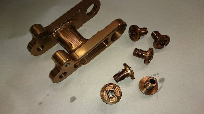 [/img]
Nice!! Very good work 🙂
That's was a good read catching up over the last 3 weeks - good job!!
Blimey that looks great!
Is that 'Kashima' colour to match the shock.....?
Thanks guys. Yeah, stumpy, that's the plan. Hopefully it'll be a good match..Thanks again for all your help with the CAD, much appreciated!