Some of you may remember [url= http://singletrackworld.com/forum/topic/carbon-fiber-repairs-worth-it ]This Thread[/url] Where I ended up acquiring a Broken Carbon Merida frame, I thought I'd post this follow up as I've not repaired any structural composites before, this has turned out better than I'd expected, and it's nice to share...
Here's a shot of the busted stay it when I recieved it:
[img] 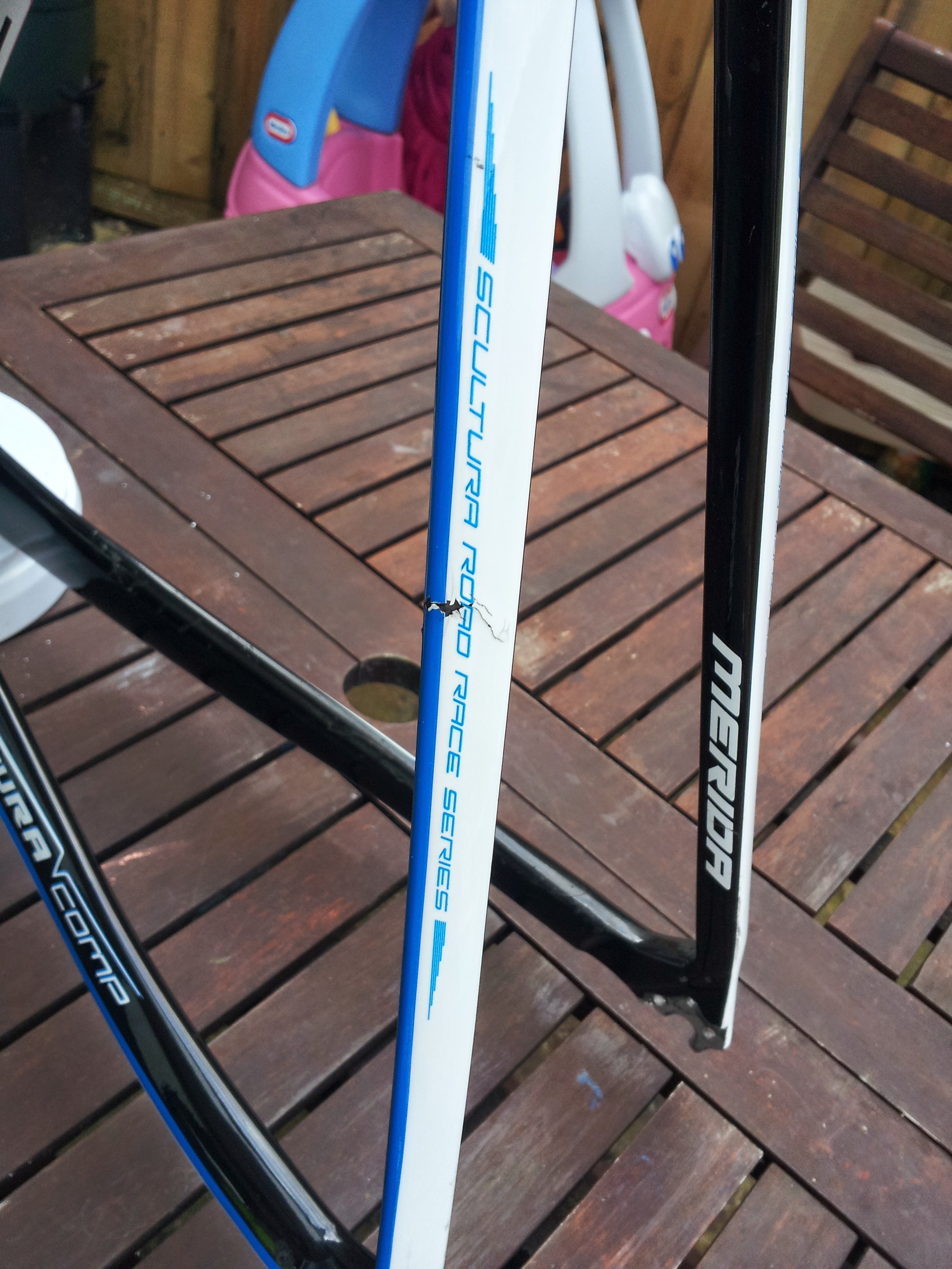 [/img]
and after I stripped the finish:
[img] 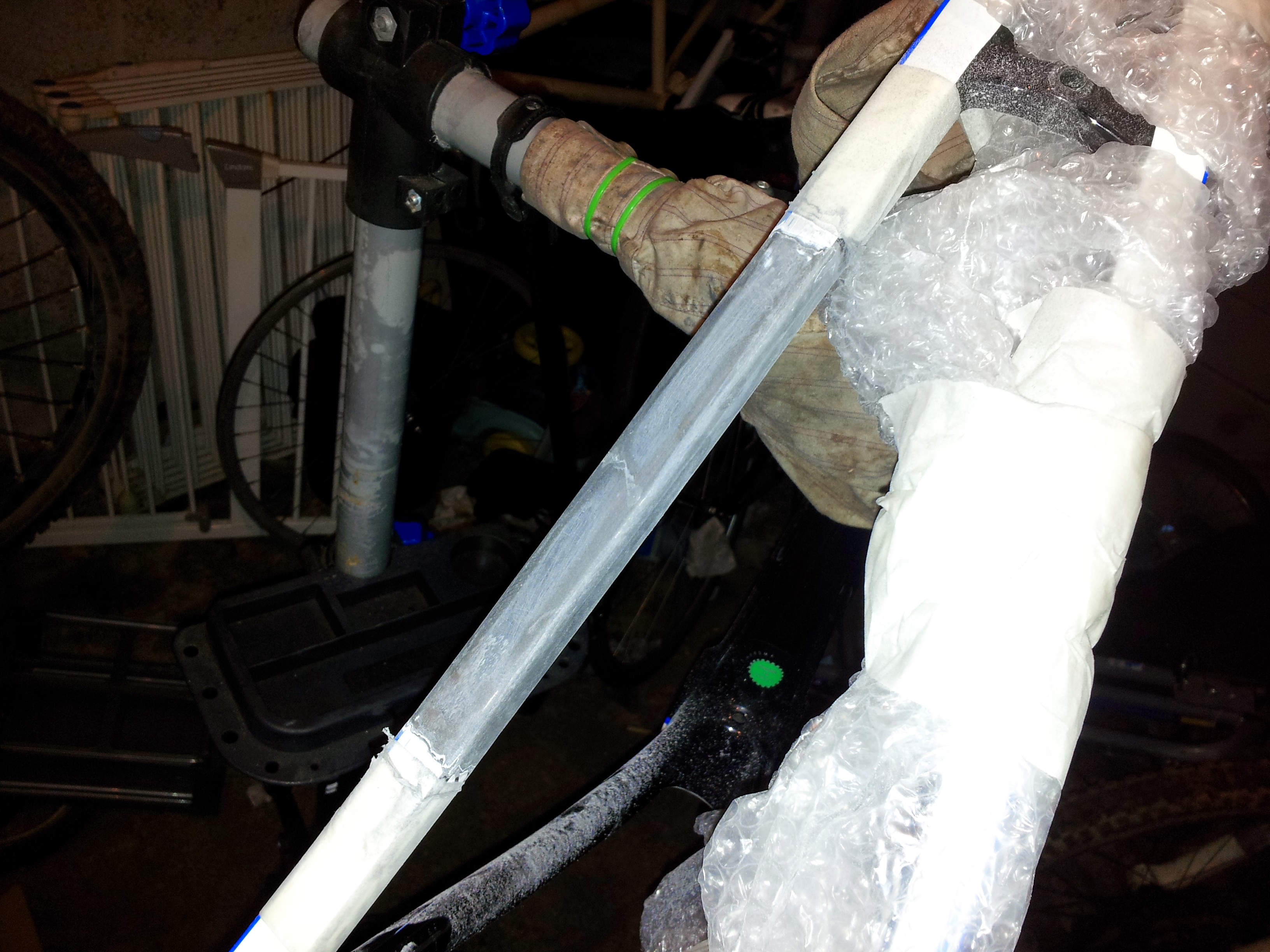 [/img]
and after I dremeled out the damaged area:
[img] 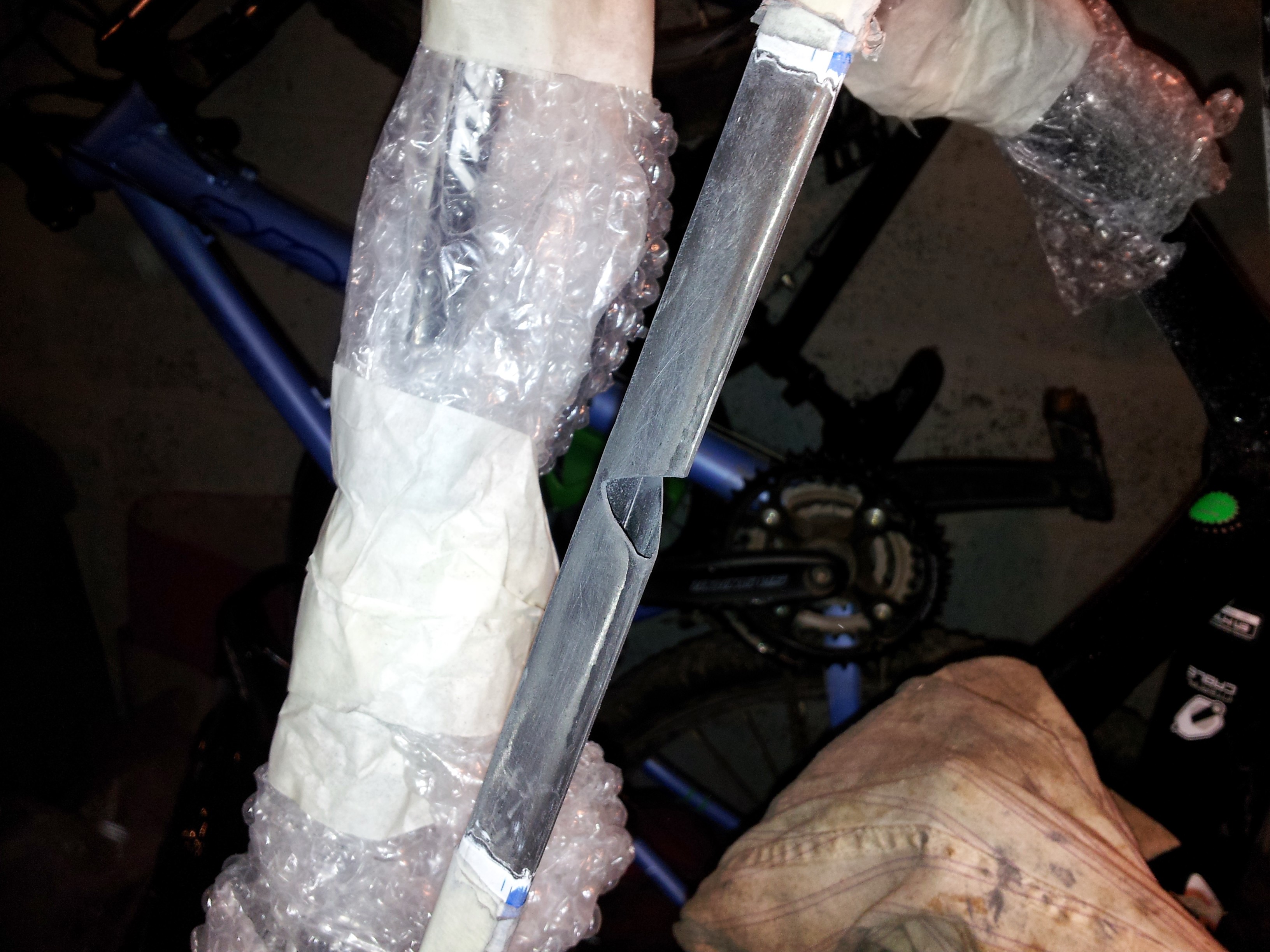 [/img]
About ~ 1/3rd of the seat stay was cracked, rather than opt for the "Splodge on some gel coat and a patch" approach I've gone a bit OTT.
I took the Stay right back to the bare composite, removed the damaged section, built a support structure and then Wrapped the whole mid section of the tube several times to bridge the damage.
The Bridging was done by epoxying in an insert:
[img] 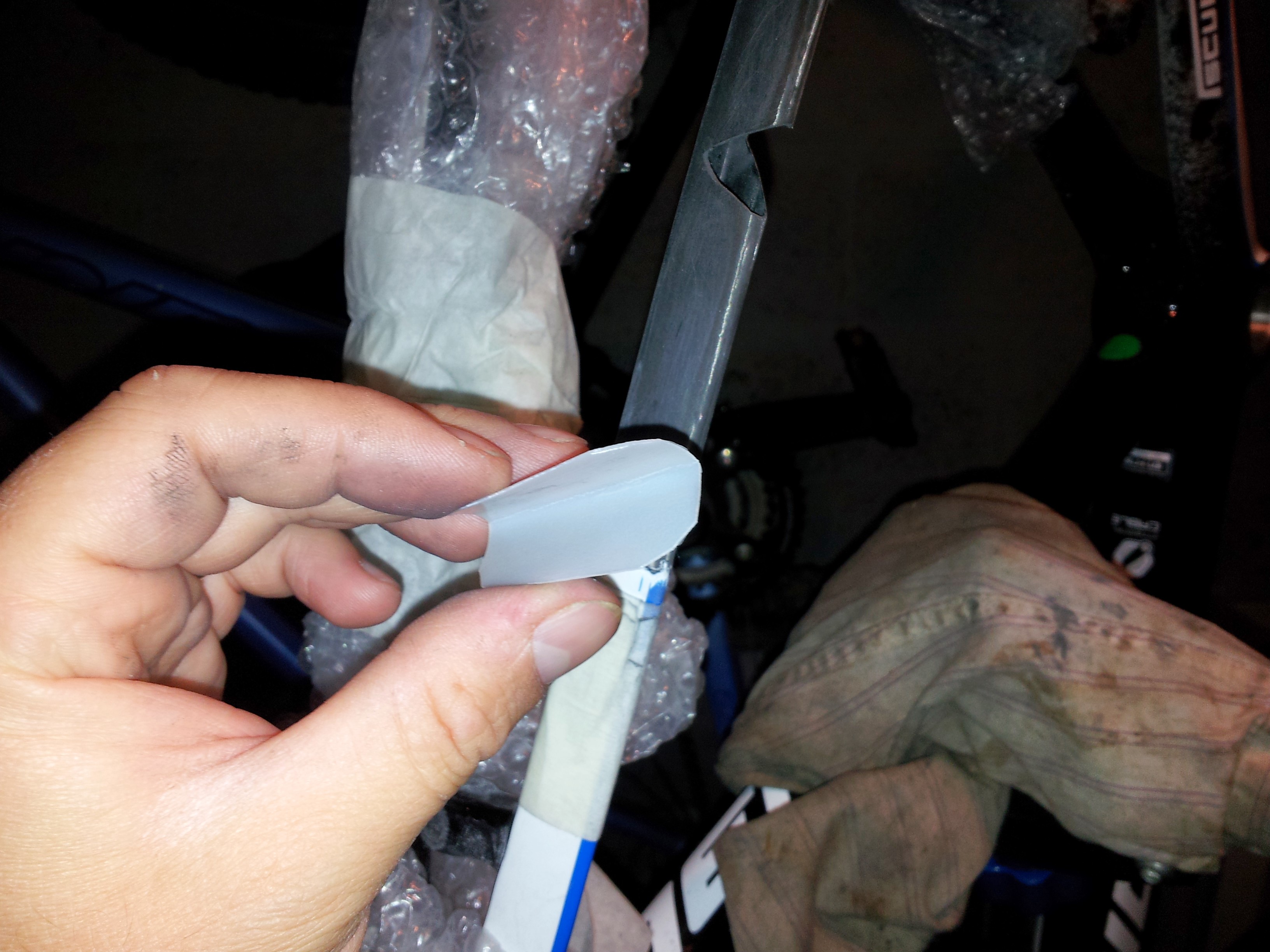 [/img]
[img] 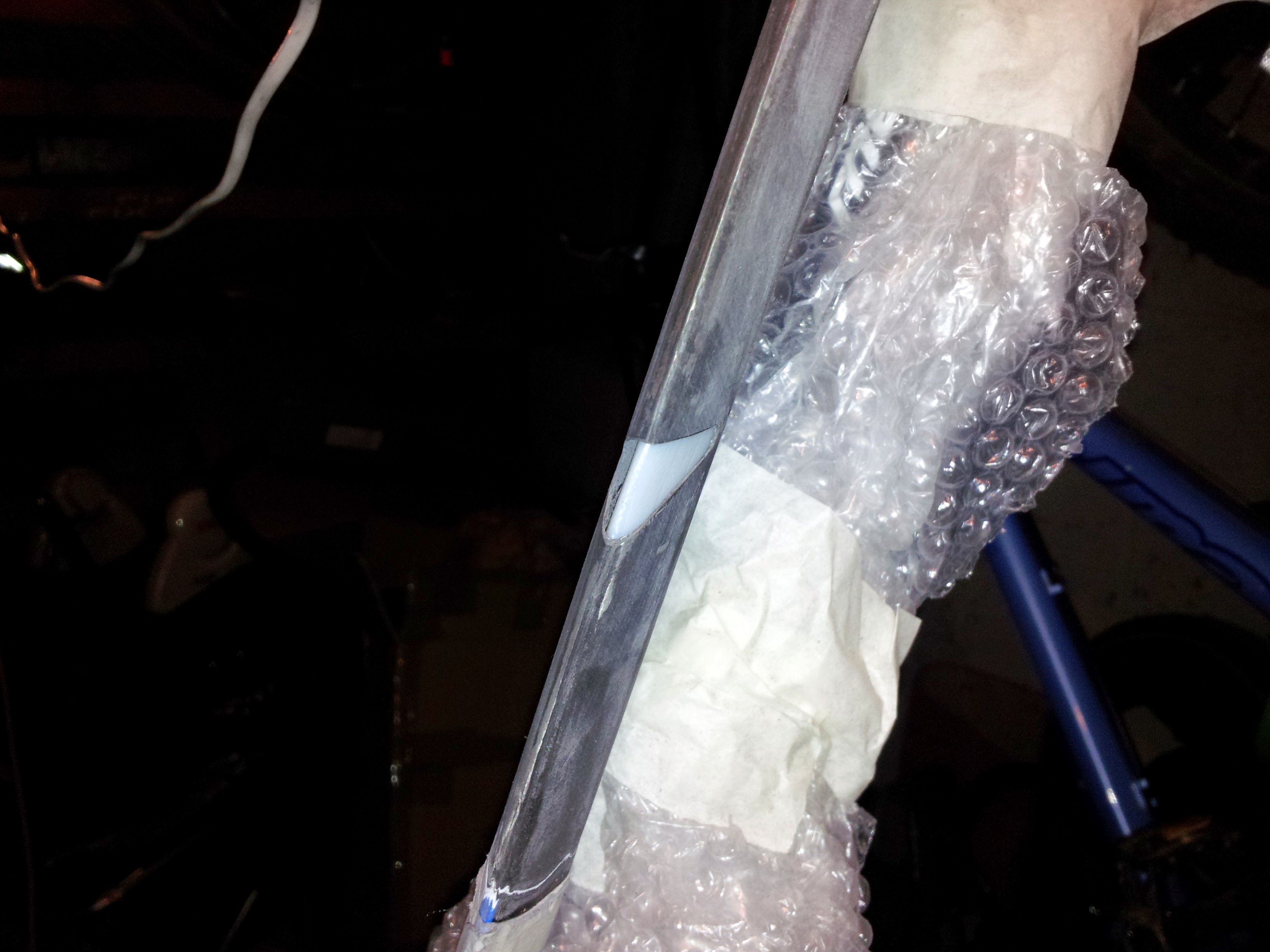 [/img]
I made this from an old bit of milk bottle (no really), this was epoxied in place and then I used a thickened epoxy to to build up support flush with the original tube.
I then laminated several layers (probably too many TBH) of Carbon on top of the support/original tube, over an area about 3" either side of the damage.
I used the poor-mans, electrical Tape compression method rather than proper vacuum bagging, as I simply didn't have the kit, it's probably quite resin rich as a result, but I'm relying more on the quantity of additional material and the large area of the repair "Splint" to transfer loads safely. I didn't take any pictures of this bit as I was a bit too busy and didn't fancy getting resin all over my phone...
This is how it eventually turned out:
[img] 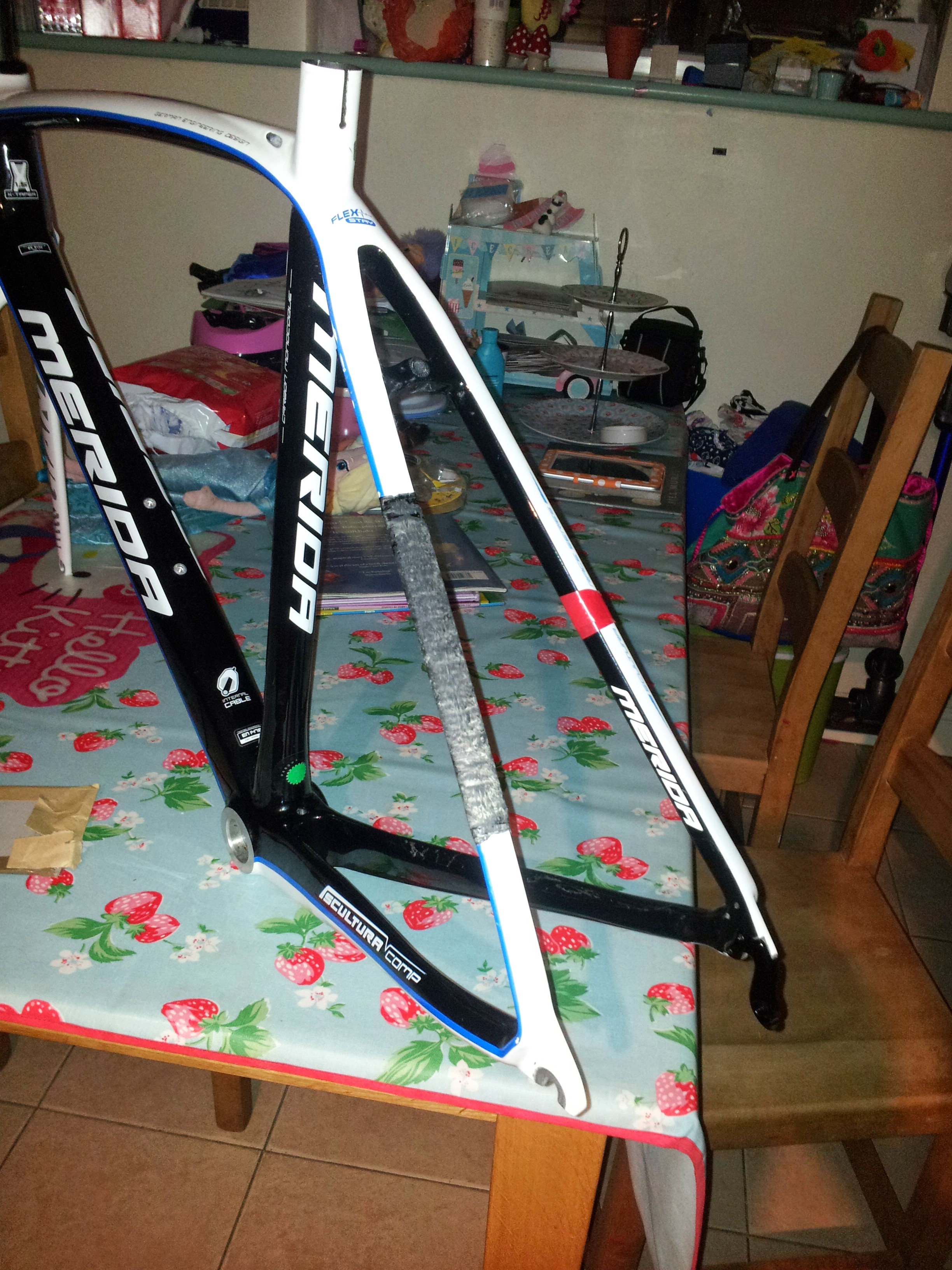 [/img]
A bulky but not too shabby repair IMO.
Assembled bike (with seriously neglected garden):
[img] 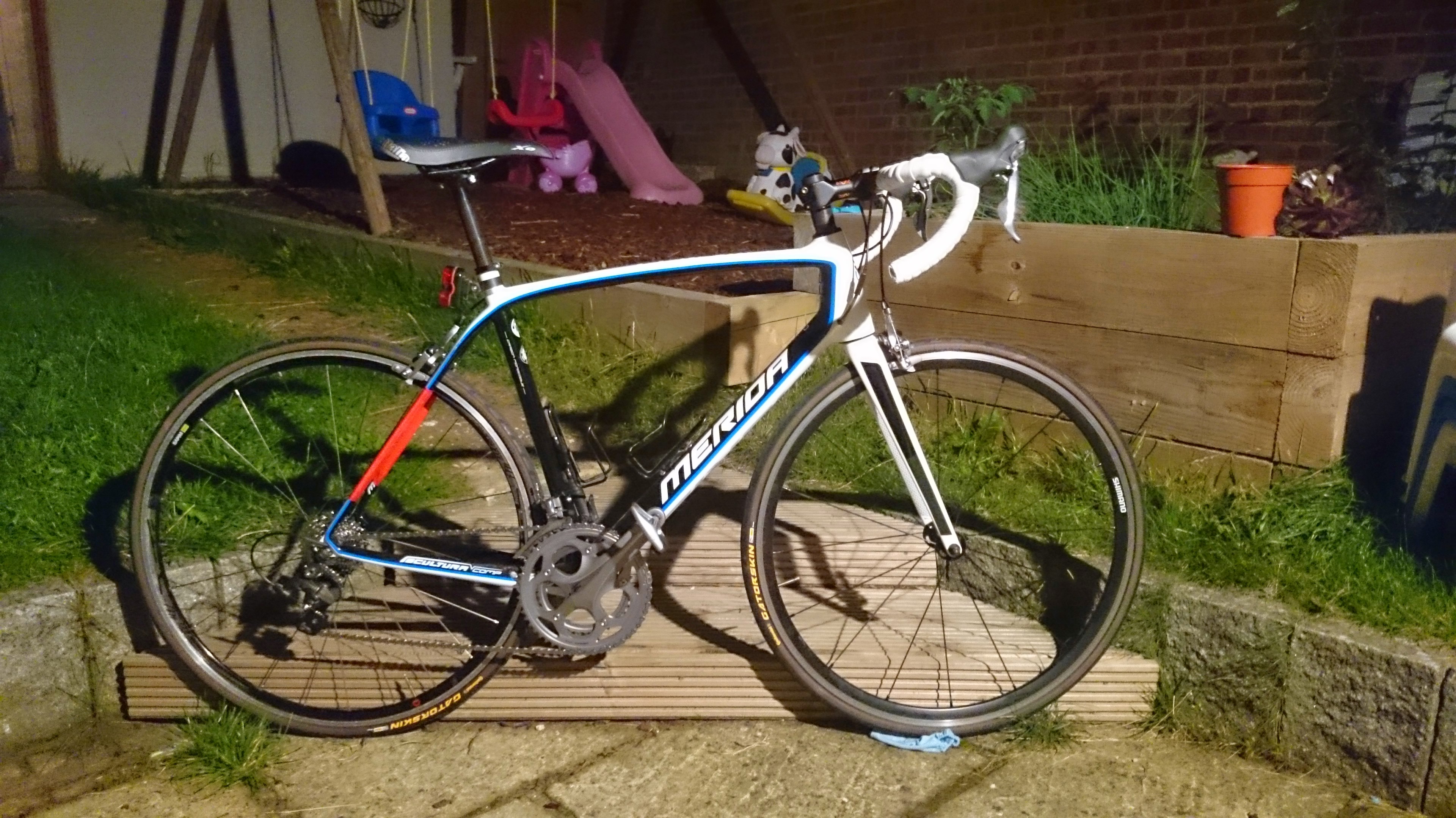 [/img]
Rather than paint over the repair I've just wrapped both stays in cheap reflective vinyl for now which I can peel back to inspect the repaired area should I need to later.
It's first Shakedown ride was on Saturday, I was expecting to hear cracking and creaking noises from the back end, not a bit of it, 27 odd miles with the tyres pumped up too hard, clattered it through a pot holes and over rough surfaces and bunny-hoping over a few drain covers, not a peep from the frame, it feels pretty good...
Buying the frame and repairing it has probably cost me about ~£120 (I did have most of the material to do it beforehand), so it was a worthwhile exercise. Though it was mostly a fun "Learning exercise" TBH... We'll see how it's going in 1000 miles.
Nicely done, be interested to see how the repair holds out over the winter.
Me too 😯
Agreed, why remove such a chunk of frame though? I'd have been inclined to just patch over the top?
@ njee20 - It probably would have been OK if I'd done that, The trouble with splodging epoxy over the cracked area and patching is that you can't be too sure how well you've fixed those de-laminated fibres and as I couldn't get at the inside of the tube I couldn't apply epoxy from the inside either, so I chose to completely remove the damaged area and bridge it, like I said it's probably way OTT, but it's a first attempt/learning exercise, should I ever repair another frame I'll probably try to keep things a bit more minimal.
Needs more spoon.
Next project will have more spoonage...
Yup, a spoon would've sorted that
TBF I did use a milk bottle, so It still has that element of "STW professionalism" about it IMO...
Organic Waitrose milk, I trust.
Chapeau - I like that!
Rather than the bit of bottle, I may have been tempted to blow some medium density foam in the tube and then sand it back to the tube surface - as well as giving easily finished surface, this would have added some buckling stability to the inside surface of the (now truncated) tubes. I see why you've done it, but I'm kinda with njee that (even if you'd cut out 'a bit' of the damaged tube) leaving the fibre whiskers exposed would give you better load transfer into the existing tube. Even in non-bagged/pretty agricultural tube joints the recommendation is to roughly machine the surface to expose the fibres before bonding....
....having said all that, with enough added material, I'm sure it'll be fine.
+1 njee but good work doing it
You're a brave man 😕
Not really. This 'carbon fibre is doom' stuff is silly. It's far more repairable than alumininium and far easier to the home mechanic than steel.
Besides, it's a seatstay. It's a very easy point to repair if you're willing to have a little extra material added.
Good effort! Looks like you did a thorough job on it.
I guess a regular inspection would be sensible for a while, but no reason why it shouldn't hold up fine. To be honest, given that you probably erred on the side of caution, it could well be stronger than the surrounding tube.
When I saw the first photo I thought it was a set of carbon forks. 😯 😯 😯
But now I see it's the stay, so that's OK.
8/10 would ride that [with elbow/kneepads the first few times].
@bristolbiker - I did think about a foam insert, or expanding foam, but once built up flush with epoxy the milk bottle made a pretty stiff support and its quite a ridiculous layup on top of all that TBH,
I put 2 layers of 200g 90/90 plain weave aligned with the tube, sanded those back and then used 100g UD:
2 layers +30*
2 layers @ 0*
2 layers @-30*
2 layers @ 0*
All the UD layers were done in one go, there's quite a bit of material in there, I stopped short of doing a "Cosmetic" plain weave layer on the top as it was already getting quite chunky, plus I just couldn't be arsed...
I took some of my inspiration from [url= http://www.instructables.com/id/Repairing-a-Carbon-Fiber-Bicycle-Frame/ ]This effort[/url], which uses 4 "Structural" plain weave layers (not sure about the fibre alignment) and a Cosmetic layer, and He reckoned he got at least another 3000miles out of it, I've added more material and aligned it better with the tube's load axis (I think)...
I like your work!
Top marks. 🙂
You own a cake stand!!! How ace is that!!! 😀
Chap on my local Chaingang has a very home made fibre glass type repair on his down tube just below head tube ..
Been same for 3 years no problems
You own a cake stand!!! How ace is that!!!
No we own SEVERAL bloody cake stands and "special" boxes for transporting cupcakes, plus lots of other Baking related crap that now clutters up the house, but she still complains that my hobbies take up too much space and I have to keep it all in the Garage*...
*(she was out when I took that picture on the kitchen table)...
😆 yup, its usually my bike cr#p that clutters the place too.
How did you achieve the compression on the pre-preg?
i did the same thing on my scott park frame with a repair kit from carbon mods. worked a treat and not a sign of any further damage 12 months on.
for the compression you use electrical tape tightly wound round the repair area. You need to add a few pin pricks to the tape here and here to let the excess resin seep out. The downside to this method is you end up with an un-even finish due to the ridges the tape leaves behind which requires a good sanding.
Basically Yeah I did the Leccy tape compression thing as shown in the indestructibles link above and on a couple of You-tube tutorials if you search.
I wet out the fabric and then roll out as much excess as I could, wrap the layer and repeat, I did do two layers of taping over the top, Sticky side out, then sticky side down on top of that as it seemed to allow me to put more tension on the tape (and hence more compression), then I pin pricked the crap out of it, it "bled" quite a bit of resin, but that's a good thing...
No Pre-Preg, Dry fabric and West system resin...
Out of autoclave pre-preg might be fun to try for some smaller projects though...
I'm under no illusions, there will be voidage in this repair, the triangular tube profile probably doesn't help, I tried my best to keep the Resin:Fibre ratio as low as possible though and like I said, there's a fair bit of material with good fibre alignment it should all help, if I were doing it again tomorrow I would probably do a few things differently now, and probably just use heavier weight UD to allow me to do it with fewer layers...
I Might look into cheap Vac-bagging set-up options at some point...
Rode it into work this morning, still seems good (touch wood)...
I was wondering about VAC bagging.
8/10 would ride that [with elbow/kneepads the first few times].
Even if it failed catastrophically it's only a seat stay, very unlikely to be the end of the world.
Vac bagging is pretty easy once you get a pump, and some peel ply to wick the epoxy away. I think you could just about do it in situ with double sided tape to seal everything.
I think, to be 100% correct, the layers should be symmetrical about the middle layer, but this was a long time when I looked into this so maybe wrong, and I'm sure it doesn't make much difference.
Looks fine and I'm sure it will be ok.
to be balanced yes you want symmetrical. For this I am not sure it's a big deal as long as ou don't have a stack of 90s then a stack of 0s or something really silly.
OP why 30 deg and not 45 deg?
tbh I would have scarfed in the joint by shaving down through the layers and working out the angles. or made a scarf patch around the whole section. You can also work out the angles of a cut chunk by making cuts at 0, 90 and 45 deg. The layers look different and you can work around the 3 edges and suss out the layup. Have to do it when technicians layup wrong and they try to blame us for distortions.
OP why 30 deg and not 45 deg?
I asked this very question on Talk composites and was told 0 and 30 degrees better aligns to the sort of torsional loading frame members see in a bike frame, my initial plan had been to cover 0*/30*/45* and 90*, but I was put straight...
the two layers of plain weave I used effectively mean I have some "Wasted" fibres at 90* to the tube axis which aren't really doing much, those layers might have been more use at 45*, but I think ommiting them all together would have made more sense... hey ho, you live and learn...
from what I could tell (and I'm nothing like an expert) looking at the section I removed and breaking it up further, it seemed to indicate of the fibres are mostly aligned to the tube axis, it is apparently built a bit more for comfort than stiffness so that would make sense...
When you say aligned with the tube you mean the 0 deg axis? ie 0 deg running from drop out to seat tube junction?
When you say aligned with the tube you mean the 0 deg axis? ie 0 deg running from drop out to seat tube junction?
Yes, but it wasn't exactly an exhaustive examination TBH...