UPDATE: Reviews section refreshed, redesigned, searchable: Go take a look
Good news I managed to get the stuff posted on sat morning
had a truly horrendous drive down from Blythe 5 hours to do 114 miles.
so missed the PO on friday .
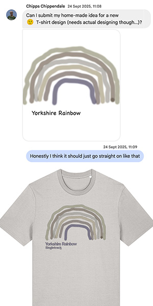
Been playing around with the AYup method of driving the leds
using 2 resistors and while not wanting to do BCT out of any sales for the minimalist build it seems not bad and will run nicely from 2 x 18650s
[IMG]  [/IMG]
trout can you get alternative reflectors with more flood?
tempted to do another for the bars. (not that i need one but more for the hell of doing it.)
you cant use these bad boys on the road. the missus was complaining it hurt her eyes from about 100ft away. at half power.
might need a bigger resistor.
I too would be interested if there are any alternative optics for a wider spread.
This websites useful if you are going down the Resistor route [url= http://led.linear1.org/led.wiz ]http://led.linear1.org/led.wiz[/url]
Trout I take it that big resistor is a 3W?
I'm sure Troutie knows this but for those who don't, the Vf of LEDs varies with a number of factors including temperature. This is why a range is given on most datasheets. When choosing a resistor you therefore need to be vary careful to balance not frying the LED against getting the most from it.
Taking extremes, assuming two fresh-off-the-charger cells are 4.2V each giving 8.4V and your LEDs are the best of the batch and running very hot (Vf decreases with increasing temperature) so say 3.1V each. That gives 8.4-6.2 = 2.2V overhead. Using a 2.2 ohm resistor gives 1A in that scenario. However, get the battery dropping to nominal at 3.7V or 7.4V for the pair and your LEDs aren't so go so say 3.4V each you only have 7.4-6.8 = 0.6V margin. You're only getting 270mA through the LED then. Even dropping the resistor to 1.5 ohm which would be nearly the 1.5A limit of the XPG under the initial conditions then you're still under half an amp under 'normal' operating conditions.
It does have the nice feature that the drive current drops with battery voltage so you get a gradual dimming.
Carrying on Troutie's good work of doing me out of a job you would actually be better with a linear regulator for the two-cell job. Over the whole range the efficiency would about equal out and the 2.2W it would have to dissipate worst case would be possible at a pinch. You'd need a low drop one though - no point using an LM317 as the drop is worse than with my circuit.
Hey Dont worry Steven I am only playing around to further my own knowledge so your drivers are safe and the easiest way to drive the leds .
just using the resistor approach means limiting your battery choice too .
The light I have just built has a 1.5 ohm and a 3.9 ohm and gets around 1.2 amps at 8 volts or 400 ma on low . not had a real play yet
but the resistors get very hot which is why they are glued to the case to shed some heat .
I just got the £20 kit from Troutie today. Thanks!
But I've realised its a little above my tech ability and that I dont really have time....
If anyone wants it let me know, I'll send on for the original £20 for anyone that wants it!
damo2576, i will have the parts off you. im sure i will need a second set
Just processing any orders for those who paid over the weekend and will update the group on what is left once they are done.
Could anyone who ordered by about Friday lunchtime please let me know if they have received their stuff and if it is correct - I've already mucked up one order so I hope I haven't swapped two over or anything daft like that!
Quick update on the holders. Payments and requests have left me with:
3x 4 way
10x 2 way
2x 1 way
Still about 10 kits left.
Hi BCT
Are there any 2 Way holders left? If so how much?
Doug
Stephen / Chris, parts received ok thanks.
thesurfbus - prices are listed a few posts back
BCT - I have received a 'small package' at the office, though not sure whether that will be yours or trouts until I am back in office. Will let you know as requried.
All the bits are now here (I think). Just been to maplins to get the box and some silicone sealant. Just got to put it all together and get the batteries charged up. Not riding til Sunday night so got a bit of time to play with it. Only going to use the copper slip stuff for the heatsinks, havn't figured out how I am going to attach the driver to a heatsink yet, probably just use some clips.
Going to try with an old 8.4V 2400mA Ni-Cd battery as that is what I have available, but will probably switch to an 18650 pack later. I have read through every single post again to make sure I havn't missed anything so hopefully I won't have too many issues, and I should have a working light by the weekend! 😀
How is everyone elses lights coming on? There must be a few more out there that have been finished, there don't seem to be many pics of finished lights considering how many people have got the kits? Are people still using this as a headlight, or as a handlebar mount?
Hopefully Adam will be along soon with more detail but a quick warning for those of you building this up.
It is worth checking with a multimeter that there are no shorts between the LEDs and the case. The panel you mount the power connector on will be live to whatever potential the outer barrel of the plug is wired to. If the LEDs are shorted on the case when you screw the back panel on you may well end up with a short which can destroy the driver.
I can't remember where I bought them from but at work I have some insulating washers for TO220 transistors where the bush is a moulded part of the washer. It is very easy to trim these to size to give a fully insulated bush for the mounting screws. If I work out where I got them I'll let you know - it doesn't look like it was Rapid though as their website doesn't list anything like that.
hi there just to confirm that I have received all the parts thanks trout and BCT. Bring on the building.
They're ALIVE! 😀
Just the initial hook up, so got to work on the case, weatherproofing and the bar switches.
Glad I used pigtails for the power instead of sockets. Just one less thing to worry about!
Interesting to see how the current rises as I drop the volts on the bench power supply!
Well done bobblehat 8)
might do well with extra weatherproofing with the rain thats forecast this week.
Bobblehat,
Oh no, I jumped in and purchased the following from ebay before reading your reply....
...Arctic Silver Thermal ADHESIVE 7g
NOTE: Even though Arctic Silver Thermal Adhesive is specifically engineered for high electrical resistance it should be keep away from electrical traces pins and leads. The cured adhesive is slightly capacitive and could potentially cause problems if it bridged two close-proximityelectrical paths.
I imagine the guy'll do a swap, one learns 😆
Just use touch up paint over the contacts before you use the adhesive, that's what I did.
Sounds good Lipseal. It's only the 2 little exposed contacts on the back of the driver board that may need sealing. I doubt that it's a problem really, but no point taking chances! The adhesive shouldn't get anywhere near the 5 main solder pads to be a problem .... not unless it's ladled on ... which is not recommended.
I'm mentally planning the next build .... a hub dynamo version. Got the LED's & reginas on their way via Damo .... sorry Norcbot. Anyone got one or two spare Hammond end panels to sell ... any colour/type?
Finally got some pictures sorted of build and finished light. Its a bit rough around the edges but I'm very pleased with it. I took it out for a ride last night, bout an hour and a half and was massively impressed with the amount of light it throws with a throw of about 30-40 paces. I did try taking some pics with my phone but they didnt come out very well at all 🙁
Heres my pics then 🙂
Heatsink with holes drilled and threaded & copper slipped.
[IMG]  [/IMG]
Heatsink with LED's attached.
[IMG] 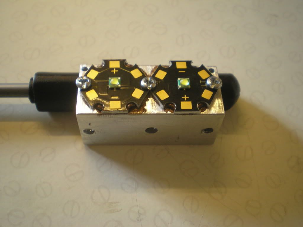 [/IMG]
Heatsink and driver assembley all soldered and siliconed.
[IMG]  [/IMG]
Finished build.
[IMG] 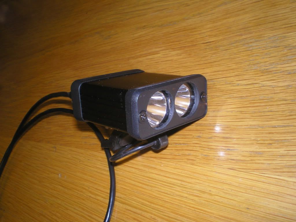 [/IMG]
Mounted on bars.
[IMG]  [/IMG]
[IMG]  [/IMG]
Its currently on my helmet, will get some pics up of that later on.
Massive massive thanks go out to Chris and Steve for organising all the kits and putting up with all my stupid questions and thanks to everyone else who has given advice throughout this thread.
😀 😀 😀
Nice one I hope you enjoyed doing it. and get a lot of pleasure riding with your own creation .
any estimate on time. and total cost.
Troutie
stayhigh, did you glue the driver and heatsink straight onto the plastic back panel?
Amazing really when you see the size of the led's they could be so damn bright 8)
Good work High, its amazing what you can do when you put your mind to it, and an even a mega grin factor when biking and asked whose lights you are using 😛
Getting on with the build up here in sunny [cough] scotland. I don't have any thermal glue for the driver heatsink, is there anything else that i can use? It didn't matter for the LEDs as the screws held it in place over the copper slip, but there is no space on the driver for screws!
Can i just use another sort of glue to attach the driver, or will it burn into flames when it gets hot? Help much appreciated, soldering challenge to begin tonight which should be interesting! One thing I have noticed is that i don't think there is enough space for the driver, switch and power socket on the backplate (as seen in stayhigh's post above) if you got the slightly larger switch from BCT in the second batch- I might be wrong but looking at it it all seems too close. Just means I will have to use the main body of the box as the heatsink and double check for any shorts.
I did thoroughly enjoy building the light up despite a couple of traumas with the build which were down to hamfisted enthusiasm on my part . I'm thoroughly looking forward to getting started on the next one over the weekend, it will be easier having already done one.
All in the pair will have cost me around £80 (led kit x2, driver kit x2, hammond x2, AAA from ebay, silicone adhesive & mixed screw set from Maplin and a helmet mount) which I think is fantastic value for the amount of light it humps out and the satisfaction of making it myself.
I'm not sure on the battery runtime yet, I'v done and 1.5 hour ride with no sign of fade and no heat build up either (helmet mount). I'm going out tonight for 2 hours and confident it will cope.
bigjim: I used AAA to bond the driver onto the bback plate. I used the skeletal end piece but thinking of using a plastic one for the next build. I cant see why the AAA wont bond to the plastic.
defaultslipper: You maybe able to use araldite instead of AAA. If you have pc shop near you you could see if they have any thermal paste for cpu's?
defaultslipper - you could consider mixing some metal dust (file something down and collect the filings) with an adhesive. I do know Araldite starts to soften at about 100C but then the driver shouldn't be getting that hot anyway!
Be aware that this would probably be electrically conductive though.
A 'normal' adhesive would not transfer heat to the metal plate. They would be unlikely to burst in to flames, depends how hot it gets! Most adhesives are good for 70C plus and the PCB shouldn't be getting that hot.
Light is done and i really pleased with it, a little ruff around the edges (damaged a reflector by melting it a little with the exhaust out the side of the soldering iron) i think less speed and more haste was in order. Good luck to the people fitting it in to a small case cut mine down to 50mm and it was tight. would have made it easer to have had sorter cable between components. Off to got test it 😀
Use a 9V power supply from work and it was fine, just neeld to go get a replacement switch, boot and box.
Would a block of mobile phone batteries wired in series do the job. They appear to be about 3.7v so three would be around 10v and still compact.
enjoyed reading the thread and very tempted to give it a go.
my only question is regarding the battery's required.
what's best to go for on a budget and/or DIY??
what voltage and mAh do i need for the hammond light?
Puntopete ... what you already got?
If it's a battery of over 7.2 volts and capable of giving 1 Amp for an hour or longer then you have a starting point!
If you've got nowt and want the cheapest option, what about 8 * AA eneloops or 8 standard NiMH AA cells and a cheap holder from MAPLIN or elsewhere and any 4 or 8 cell NiMH charger from just about anywhere?
Teap0t's driver needs a minimum of about 1 volt above the Vf (forward voltage) of the 2 xp-g Leds .... which is about 3.3V each or 6.6V for 2 Leds at around 1 Amp. So your power source needs to be (ideally) 7.6V minimum, and capable at giving 1 Amp for as long as you want the light to be on.
8 Eneloops at 9.6V will power this setup for about 2.5 hours at full power of 970mA. If you set it up with a lower current, you'll get a longer run time. You might get away with using an RC 7.2V Sub-C pack, but that's a bit experimental at this stage .... not yet tested.
The other popular way is with 18650 Li-ion cells at 3.7V each. The set up seems to work OK with a standard 2-cell pack of 7.4V ... I've seen Lipseal's build working beautifully with this 2-cell pack. It was impressive!
Theory says you're better using a 3 cell pack at 11.1V or higher .... Teap0t's driver will handle all of these variations, but as I said there is some caution with using the lower voltage packs.
If you are old school and have any sort of 12v Lead acid set up that you are willing to carry on your bike ... that would do also!
Evening all.
Stumbled across this thread (and forum) whilst researching the Magicshine lights, with a view to purchasing one. I've spent the last two evenings reading, Dealextreme have just lost an order.
Hats off to Troutie, CK, BCT and others who have shared their valuable knowledge and time, thank you gentlemen (or gentleladies, you can never tell on t'interweb :D).
I'd be very grateful if I could be added to the list for the following
Mr T: 2 LED stars + reflectors and aluminium bits and bobs.
Mr BCT: 970mA driver board (3 way, that's hi/lo/off ?), 2 quad 18650 holders and switches etc.
thanks for your reply. i haven't got anything yet, so starting from scratch.
800 posts 🙂
BCT; 18650 holders recieved today, cheers.
Still got plenty of leds and reflectors
had a few mails paying but cant put a stw name to them so if you want some then mail me
stayhigh - What type of drill bit did you use to drill the two holes in the black plastic cover for the LEDs, I want to go down this route but need to buy a suitable drill bit?
thesurfbus
Flicker ... just for info, the switch will operate off/high/low (or low/high/off depending on which way you wire it), but can't be set up for off/low/high with the normal switch. The centre position of the switch isn't connected to anything and that gives "high" with this driver.
StayHigh.
I see from your pics on page 20, that you appear to be using the half clamp and rubber ring for a handle bar mounting solution.
How is that wokring out ?.
🙂
Finally picked up my trout pack from the office - thanks so much trout.
Such tiny LEDs. I wonder if I could upgrade my Joystick maxx to use one of these instead of the P4....
Here are some beam shots from my ride to work last night. The quality isnt great as its a camera phone but you get the idea.
Low beam
[IMG]  [/IMG]
Full beam
[IMG]  [/IMG]
[IMG]  [/IMG]
thesurfbus: I used a 20mm flat wood drill bit to do the holes in the plastic bezel. Its kinda fan shaped with a point sticking out. I had considered getting a cone shaped one but the flat bit was to hand at the time.
IIRC on CK's light the holes are chamfered which I think looks neater b ut not sure what would give you that finish. I only have access to a cordless power drill but I imagine a pillar drill would also give a better finish.
Luminous: The bar mount seems to work ok. It was used like that for a short ride and seems stable enough however the light is currently helmet mounted (cateye helmet mount)which is very good.
Anybody tried mobile phone batteries for something like this.
Four batteries strung together would be small still, even six together would be small.
I presume a charger would charge them up.
surfbus, I'm going to make holes in the plastic front too, was thinking of drilling them out roughly then filing/sanding down to a smoother finish. I'm making this to see where I'm going, not to look at, so not too fussed.
going to make a start on this this weekend! not got the driver kit yet but will cut the case down, drill holes etc.
All bits arrived safely, just need to sort the box, batteries, soldering, etc. Thank you very much troutie and BCT for all your efforts helping us all.
Bobblehat......Cheers for the heads up. I'm considering wiring it up to give Hi/med/low and off using two switches. I'm looking to use the setup for commuting, as well as leaping about like a damn fool in Delamere forest 😀 , so the three settings could come in handy.