- This topic has 43 replies, 11 voices, and was last updated 13 years ago by rootes1.
-
mechanical engineers advice sought
-
iDaveFree MemberPosted 13 years ago
is there a simple mechanism which would allow progressive resistance against rotation in both directions of a short length of round or square section steel?
so, for example, 15cm length of 25mm diameter tube has integrity horizontally and vertically but rotationally allows movement against resistance?
thanks, you’re all lovely
PS – google is broken
LuminousFree MemberPosted 13 years agoJudging from what you’ve written, I think you’re describing a desire for something like a torque convertor.
The harder you push, the more resistance yes ?.
Similar principle to a fluid based torque convertor for an automatic car.
I’ve never used a “turbo trainer” but don’t they have similar devices, either employing fluid or air to generate the resistance, the faster you pedal ?.
I’d have thought there should be Companies around that supply this type of torque resistance unit, off the shelf.
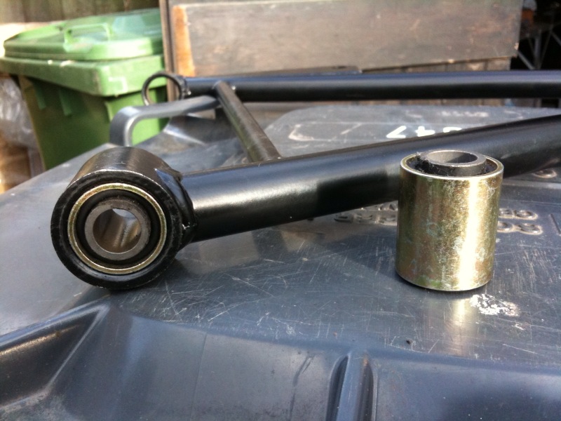
TandemJeremyFree MemberPosted 13 years agoMetalastic bush? Or have I misunderstood what you are looking for?
 The inner part will twist against the outer getting progressively more resistance and will spring back in a damped manner. Using in old british motocycles suspension amongst othre things. Reasonably rigid along the length of the cylinderLuminousFree MemberPosted 13 years ago
Yeah, not fully understanding the requirement, I was thinking viscous rotational speed govenor or rotary viscous damper myself.
❓
nickjbFree MemberPosted 13 years agoSounds like a rotary damper. You can omni directional, bi directional full rotation units. We used to get them from Wales Fluid Power. Big ones are quite expensive.
iDaveFree MemberPosted 13 years agoTJ may have it if the inner bit could be threaded, which I’m sure it could – the movement only needs to be about 15mm from centre at the end
bigsurferFree MemberPosted 13 years agoUsed to work for a company making rubber bushes, they were very widely used on pretty much all car suspension of cars gone by. I am sure you would be able to tap the center carefully as you will be working against the rubber. Your best bet is to go to a decent motor factors and ask if you can look through their stocks for a good fit size wise. If you can match the OD that you need then it would also be possible to press in a threaded insert into the middle.
It all depends on how much force you are applying to it, they are designed for shock loading not rotational force, they should be well bonded and will take quite a bit of rotational force but they are normally used with a free axle running through the middle.
LuminousFree MemberPosted 13 years agothe movement only needs to be about 15mm from centre at the end
Is that radial movement, axial movement ?, what direction is your 15mm of movement.
Are you describing a rotary movement of 15mm, radially ?.
What is rotating, the inner or the outer ?.
bigsurferFree MemberPosted 13 years agoYou can get left and right hand threads, although a left hand tap and bolt will be quite a bit more expencive than a standard one.
LuminousFree MemberPosted 13 years agoIt all depends on how much force you are applying to it, they are designed for shock loading not rotational force, they should be well bonded and will take quite a bit of rotational force but they are normally used with a free axle running through the middle.
My thoughts exactly. Wouldn’t of thought it would have many cycles in it if you rotated too far on each cycle.
iDaveFree MemberPosted 13 years agoLuminous, rotational movement from centre
there needs to be no other movement – nice and stiff if you like
thom – yes it might undo, i’d prefer it not to after assembly
one end is fixed, the other needs to rotate in both directions?
If anyone would like to get involved in designing a new product, which I have already got a market for…… 😯
TandemJeremyFree MemberPosted 13 years agobigsurfer – on british motorcycles they were used in rotation firmly clamped. My BSA has them for the read sus pivots and greaves used them in leading link pivots. 30 Degreeish rotation using the rubber in shear.
Swingarm clamped tightly to the inner steel bush and outer clamped firmly in the frame – gave a maintenance free pivot. Some designs even used the rubber as the spring
molgripsFree MemberPosted 13 years agoI’d love to, but I’m only a Physicist not an engineer so I might not be useful 🙂
How much resistance, and what kind of size we talking about? Some kind of metal torsion spring perhaps?
LuminousFree MemberPosted 13 years agoNot sure there TJ, on the other side of that wheel is a brace, hnaging from the right hand fork leg.
That bush is doing the usual job of a suspension bush, nothing rotational.
Rotating it would put the rubber and the adhesive into shear. Very small amounts of rotation may be tolerated, but cycle it too many times and either the rubber or adhesive would fail.
iDaveFree MemberPosted 13 years agoI’d be looking at having ‘quite a bit’ of resistance – to the point of being ‘quite stiff’. The ‘unit’ would be 150mm long. Approx 25-30mm diameter.
bigsurferFree MemberPosted 13 years agoThink luminous has a point, my experience is that when the axle in the center of the bush siezes the rubber degrades very quickly.
http://www.psluk.co.uk/images/automotive02.jpg the tall bush in the center is from a Jag steering column I used to work for this company but they have since closed the factory that I used to work for so I have no contacts their. From memory the steering column bush had a max of about 20 degrees rotation before it hit deadstops so as not to damage the rubber.
TandemJeremyFree MemberPosted 13 years agoLuminous – It does.
The rear suspension bush on my motorcycle does exactly that the only movement in the rubber in shear, its 50 years old, hundreds of thousands of miles and its fine. The swing arm is rigidly clamped to the inner steel bush the outer to the frame
That fork the only springing is the rubber in torsion. the other bits you see are the linkagesd for the brake torques
bigsurferFree MemberPosted 13 years agoLooks like TJ has the perfect solution then, I would either pick TJ’s brains about specific sizes or talk to a few classic bike spares companies.
the STW massif always gets their in the end.
TandemJeremyFree MemberPosted 13 years agoBigsurfer – the invacar used rubber in torsion suspension as well and it was common in motorcycles of the 50s and 60s.
LuminousFree MemberPosted 13 years agoTJ.
Is that bike on a stand ?.
There is very little movement going on there, there would be more suspension from tyre deformation than from the bush, hence why it may have done some miles.
🙂If bushes such as that were effective in the way you are claiming, then we wouldn’t need springs or torsion bars, etc.
As BigSurfer says, bushes of that nature are there to absorb radial loads, as they do in automotive suspension.
We don’t use them for rotational control or damping, because after many cycles, the rubber or adhesive would fail.
Rubber usually best for tensile applications, such as our inner tubes.Cheers
😉rootes1Full MemberPosted 13 years agoSwingarm clamped tightly to the inner steel bush and outer clamped firmly in the frame – gave a maintenance free pivot
Yer used on lots of suspensions designs..
Hillman Imp front wishbones and rear trailing arms attached to body via metalastic bushes.. lots of other cars are the same from that age and for those designs that do not use macpherson strut, but even then such bushes are used for track control etc..
also people use them for wishbone mountings on Locosts (Home built Lotus 7 type cars) where you what a bit of cushioning (instead of using spherical (Rose) joints
see:
simple things, cheap and work well (bstid to get out of arms somethings when they have rusted in mind!
often replaced by polyurethane bushes for more ‘performance’ but these do not have the inner and outer metal bits bonded to the poly bit so not quite the same.
TandemJeremyFree MemberPosted 13 years agoLuminous – I have taken these things apart. Have you?
Tehy do work like this hand have done in many applications over many years.
FFS man – my BSA rear swingarm pivot is made like this and has done hudreds of thousands of miles without failing.
that greavbes is rubber in torsion suspension
molgripsFree MemberPosted 13 years agoI’d be looking at having ‘quite a bit’ of resistance – to the point of being ‘quite stiff’.
Are we talking people kind of weights, like in a bike? Or car kind of weights?
bigsurferFree MemberPosted 13 years agoI have to agree with Luminous, they are used in car wishbones and lots of other places on cars, but they are a pivot with a bit of give to remove shock and vibration, hence why they are a slightly more compliant option than a rose joint. The suspension / damping is being done somewhere else by something else.
As for the motorbikes I don’t have any knowledge of this area so will duck out of the argument, let the mud slinging comence.
rootes1Full MemberPosted 13 years agoyes in cars they are just a pivot, damping and springing is dealt with bu other means.
could see them being used as TJ suggests though… rubber is very useful, self damping etc..
LuminousFree MemberPosted 13 years agoTJ.
What do you do for a living ?
I am an automotive Engineer, working for one of the largest car companies in the world. I have worked for several over the many years I’ve done this.
You are telling me about suspension, is that right ?.
Have a good weekend.
😀Dave, if you want to chat, mail in profile.
rootes1Full MemberPosted 13 years agoalso one option would the concept in trailer ‘indespension TM others aer available!’ units..
these use rubber in compression but in the manner you need… central twisting axle within a concentric tube..
x-section though type of indespension
self damping to a degree as well.
TandemJeremyFree MemberPosted 13 years agoLuminous – I suggest you read the links I have provided.
Rubber in torsion springing was used a fair amount. ‘its not ideal as you get the same damping in compression and rebound and the laterl control is not perfect hence it is no longer used
However the basic premise of the metalistic bush with all the movement occurring in the rubber in shear was used extensively.
I repeat. My BSA swingarm pivot has this system. the outer metal part of the bush is rigidly held in the bike frame, the inner part rigidly held on the swingarm, as the swingarm moves the rubber moves in shear. thie is the only place movement occurs.
iDaveFree MemberPosted 13 years agorootes – similar to a prototype I had made a couple of years ago
Interesting….
LuminousFree MemberPosted 13 years agoVery good Rootes1
You still may need a damper, but rubber in that application could be effective, as that design goes to show.
😉
TandemJeremyFree MemberPosted 13 years agoLuminous – have you ever seen the greaves system? A bsa rear suspension bush? No
Well how do you know how it works
Did you read the links?
You are so arrogant to tell me that something I have taken apart and rebuilt does not work. Something you have no knowledge of.
molgripsFree MemberPosted 13 years agoAh yes, almost every caravan on the road has that design rootes, I believe. Very reliable.
TandemJeremyFree MemberPosted 13 years ago1Dave – these suspension bushes will do what you want and are totally reliable
rootes1Full MemberPosted 13 years agore TJ… apparently he is correct and the Greaves design was first used on those crap 3 wheeler invalid carriages…
put the design down to inventive/nuts british engineers..
(ps is it ok to agree with TJ on here?)
think that the indespension design offers better scope for what ever iDave is building….. (go on tell us)
Si
molgripsFree MemberPosted 13 years agoIt does rather depend on what it is. The TJ design would fail if enough force was put into it I think. But it could be strong enough for the application in question.
coffeekingFree MemberPosted 13 years agoBit tough trying to choose a solution when you can’t see the other contributing factors in the problem, there’s a few options out there but different additional forces/limitations could rule them out/in. No sane engineer would provide a definitive answer with such sparse info, and for that reason, I’m out (but still curious) 🙂
 The inner part will twist against the outer getting progressively more resistance and will spring back in a damped manner. Using in old british motocycles suspension amongst othre things. Reasonably rigid along the length of the cylinder


The topic ‘mechanical engineers advice sought’ is closed to new replies.