- This topic has 26 replies, 12 voices, and was last updated 7 years ago by aracer.
-
Controlling electro magnet via USB?
-
flanagajFree MemberPosted 7 years ago
The savvy ones amongst you will have gathered that I want to build a Tacx style bike trainer where the resistance of the rear roller is controlled via the PC. Plan is to basically use an electro magnet to control how many watts you have to put into the system to turn the roller.
If any hardware wizards out there can give me an inclination as to how you would do this and what is required that would be great. I am a java programmer and am planning on learning C++ to write the device driver and will call the C++ dll via JNA.
stevehineFull MemberPosted 7 years agoHow are you planning on varying the strength of the force ? Moving the magnet physically closer or by varying the voltage applied ?
If the second; you’re going to need to output across some GPIO pins; and some external buffering; then some D->A conversion to get a given signal value out and finally some sort of current drive (an amplifier with low gain essentially)
I’d be interested in how this turns out – I’ve had vague plans to build something similar for a while !
stevehineFull MemberPosted 7 years agoActually; thinking about it – if you can control the electromagnetic via pulse width modulation; that might make it all a bit simpler; then you are just turning it on and off from a serial bit stream
flanagajFree MemberPosted 7 years agoHow are you planning on varying the strength of the force ? Moving the magnet physically closer or by varying the voltage applied ?
If the second; you’re going to need to output across some GPIO pins; and some external buffering; then some D->A conversion to get a given signal value out and finally some sort of current drive (an amplifier with low gain essentially)
I’d be interested in how this turns out – I’ve had vague plans to build something similar for a while !
Fancy a project?
stevehineFull MemberPosted 7 years agomaybe 🙂 – Where are you based ? – I’m one of those evil .net coders by day; but back in the day I got my degree in Electronic Engineering …
stevehineFull MemberPosted 7 years agoAlso; quick google threw up this; so PWM could well be the way to go..
TheBrickFree MemberPosted 7 years agoI would not bother setting a device driver as in a mental module or windows driver etc.
Use an arduino or similar to control the turbo trainer. Send the arduino set points over UART but close the loop within the arduino. R
Write the pc side in what ever you want.Be aware that when controlling highly inductive loads you may need to consider some form Of snubber circuit as the. Voltage spikes can cause damage to the rest of the circuit.
flanagajFree MemberPosted 7 years agoAll of the above is double dutch to me!
Basically, what ever option is chosen the magnet needs to simulate how many watts is required to drive a given mass at a given speed up an incline. So that could potentially be a few hundred depending on the incline.
I am based in Dorset and would be happy to pay for someone to build a proof of concept.
richmarsFull MemberPosted 7 years agoYou’ll need to control a fair few amps, so not straightforward. It may be easier to drive a dynamo from the roller and adjust the electrical load connected to the output. (A bit like regenerative braking).
MurrayFull MemberPosted 7 years agoI like the dynamo idea. I can see how to adjust the load resistor mechanically (wire wound resistor and a wiper). How would you do that electronically?
richmarsFull MemberPosted 7 years agoA bit round about, but a linear actuator on a mechanical resistor.
You can get digital resistors, but I don’t know how much power you can put thro’ them.Edit, or use real power resistors and turn them on electronically. (but you would have ‘steps’ in the load.)
maxtorqueFull MemberPosted 7 years agoGet yourself a small car alternator, typically say a “100amp! unit, it’ll look a bit like this:

You need to arrange for the pulley on the alternator to be driven by the rear wheel of your bike, i’d suggest a simple friction drive, or perhaps a belt drive etc
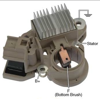
Then you need to directly short the output of the alternator to it’s own casing. This will effectively cause a short circuit, but it’s ok, all that will happen is the unit will dissipate energy as heat in the stator windings of the device. Use a nice thick piece of wire to short the B+ terminal stud to the casing, the B+ terminal is the one in this pic the finger ISN’T pointing too:
To control the load, you need to remove the regulator unit from the alternator, and drive the excitation coils directly, with a dc supply. The more current you put into the excitation coils, the higher the magnetic field strength, and the more the unit will act as a brake. Typically, you’ll be wanting to vary that current between 0.5 and probably about 3amps. However, you’ll need to keep the brushes from the regulator unit, as these push on the copper slip rings on the rotor, and transfer the current to the spinning rotor windings.
The regulator will look a bit like this:
Notice the copper brushes in the centre. You will need to get a bit medival on it’s ass, and hack the regulator about with a hacksaw to be able to directly break into (solder wires onto) the copper wires which are connected to those brushes. Don’t worry about any electronics in the unit, you won’t be using those
For initial testing, you can try with a simple power supply, like a “wall wart” or cheap adjustable DC/DC convertor off ebay. Anything where you can vary it’s output voltage between about 1v and 5v, and that can supply say 3amps of current.
Get that^^^ working and we can then talk about how to “automate” it all from your pc or with an embedded controller like an arduinio etc!
aracerFree MemberPosted 7 years agoI agree with all the above – the most challenging bit will be the electromechanical, followed by the electrical. The computer control is relatively trivial – I would say that because it’s where I have most expertise, but then the whole project is within the realms of things I do.
I’d have to look up details, but if you can control the current via PWM then just use that via a standard motor control IC. If you need proper analogue control, then you can also do that via pwm – simply use a filter on the PWM to convert to analogue voltage (you can use a proper DAC but for this application filtered PWM will work fine). In either case use an Arduino or RPi as recommended above – various ways to control those from a PC, probably the simplest is a USB to serial converter. You definitely shouldn’t be writing drivers unless one of your aims is learning to do that.
MurrayFull MemberPosted 7 years agoA little bit of digging around later, MOSFET looks like the way to go.
stevehineFull MemberPosted 7 years agoMOSFET is always the way to go when switching large loads !
I like the hacked alternator idea; my only concerns would be whether it could supply sufficient braking force and how it would cope with the heat dissipation required…
flanagajFree MemberPosted 7 years agoSo am I correct here that the approach proposed by @maxtorque coupled with the MOSFAT?
With regards to heat dissipation could a separate heat sink not be introduced.
The Tacx Fortius trainer I have has the rear motor and a separate large box. Tacx state that the excess energy created by the rider is put back into the electricity system?
I’d be happy to buy another Tacx trainer if someone fancies taking it apart and seeing how it’s done.
The Tacx units are expensive and I want to try and build one for ~ £100 / £150 . This, obviously, does not include R&D costs.
If anyone is serious then feel free to email me. My email is on my profile.
zzrmattFree MemberPosted 7 years agoMay be worth reading about “eddy brakes” as I think thats effectively what you are looking to make using the alternator above. I’m not sure if you can actually buy small eddy brakes with a control interface, I know you can get large ones as I used one when building an engine dyno a few years back.
big_n_daftFree MemberPosted 7 years agoI’d use a Raspberry pi, plenty of bits available to hack the power side
I would mix the drag side as you will never need zero drag so you could try and limit the operating range to make it simpler
maxtorqueFull MemberPosted 7 years agoA typical car alternator puts out 100A at 13.7V, that’s 1.37kW
A typical bike rider puts out about 400w.
The only issue with the alternator idea is that you’ll find it’ll need a reasonably high speed to reach it’s quoyed maximum output, however, unless you are Chris Hoy, you ain’t going to be troubling the max output!
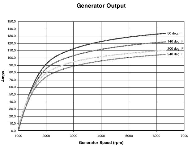
Typical output curves look like this:
Notice, they don’t start to generate positive current until more than 1000rpm is on the alternator shaft. This is because those currents are measured into a fixed 12v (or 13.7V depending on manufacturer specs) load. The alternator must spin fast enough to reach an output voltage of more than that voltage to push current forwards out of itself. This is why i suggested simply shorting the output to the case. Here, the forward voltage will just be that generated by the output rectification diodes and the I^2R loses in the stator windings, typically probably 3 volts. As such, the alternator will start to generate at a much lower speed, probably around 300rpm. Luckily, the rear wheel of your bike is large, and the alternator pulley small, so a simply friction drive type arrangement will provide a nice high drive ratio!
The alternator has a built in fan, that blows air through the machine, cooling it. This should be more than capable of dealing with the pretty puny output of the average human being!
The voltage regulator already contains a PWM driver to set the excitation current, based on output voltage, but as this is usually buried in a sealed plastic (or epoxy potted) housing it will be difficult to get to.
You will have to arranhe your own current controlled PWM output to the field windings, but as i said, start with a basic setup, get it mechanically working, use an adjustable power supply or DC:DCV to get things going, then you can work out the control details as you learn more about how it all works! (my suggestion for beginners to electronics is KISS, and just to buy already build components to save the steep learning curve of trying to do everything yourself. For example, driving MOSFETS sounds easy, but there are myriad important details, often overlooked, and often leading to disappontment in beginners!)
Something like this:
Will get you started, and you can reverse engineer and inspect that to work out how it works, without having to understand everything at once 😆
maxtorqueFull MemberPosted 7 years agoBTW there is NO point in re-circulating the riders energy back into the mains supply!
Assume you can pedal at 200W for an hr, which is going well, that’s 0.2KW hrs, which, assuming your system is 100% efficient (which it will be nowhere near because of the large step up voltage) that’s roughly, at typical price of 14p/kwhr, worth 2.8pence off your electricity bill. You’d have to pay me a LOT more than that to slug my guts out on a turbo trainer for an hour……
In terms of costs, assuming use of ebay for s/h parts where necessary:
Alternator: £10
Power supply (240vac inpout, 12v, 5A output) £15
PWM driver: £5
Arduino for control: £10
Misc wiring etc:£10Say about £50 all in
molgripsFree MemberPosted 7 years agoA typical bike rider puts out about 400w.
Not when sprinting, and sprint intervals are useful turbo workouts. I’d suggest 800w minimum, but I’ve done 1.3kw for a few seconds before. Although not on a turbo.
Perhaps not friction drive though? Nice big flywheel attached to the centre of a hub would give a great realistic momentum feel. Always fancied one of those turbos with a chain drive on a hub.
Is it going to be a dedicated bike? Given you can vary the resistance you could have a flip flop hub with a small sprocket on one side and a big one on the other and a chain drive to the alternator.
flanagajFree MemberPosted 7 years agoNot a dedicated bike. I want the unit to accept a standard 700c wheeled road bike. Needs to be quick to get the bike attached and get pedaling.
holmes81Free MemberPosted 7 years agoDon’t forget to protect the circuit from the back emf using a diode.
When getting MOSFETs get logic level drive ones.
aracerFree MemberPosted 7 years agoI’d suggest just getting a dedicated driver, as I suggested above, given the implied level of knowledge of the OP.


The topic ‘Controlling electro magnet via USB?’ is closed to new replies.