Forum menu
Can anyone help please? I have found some tables online but I have no idea how to translate them into something I can understand.
I'm looking to work out roughly what the safe load is for some timber (that I've already bought!). It's being used as a garden bridge. 2 joists 45x245mm, 3metre span. Obviously I want to know if this will be safe for 2-3-4 adults or whatever. I'd need to know the capacity for a single joist, given there is a chance there could be people stood on one side only. Also, the actual width being used will be around 180mm due to an arc that's being cut in the wood.
So can anyone help me figure out the load that C16 could take in the middle at 45x180mm over a 3m span?
Am I asking a stupid question? I've no idea really!
[url= http://www.home-extension.co.uk/tech2.html ]This[/url] might help.
That says "the imposed load will not exceed 1.5kN/sq.m". How does that relate to the weight of someone standing over a 30cm section of the joist? Or two people standing over 1m of it?
The grading will not be valid if you cut the curve into the timbers.
How wide is this bridge that you have planned?
An easy way to belt and brace this would be to double the timbers up side by side.
1.5kN/m2 is roughly 150kg/m2. Your joists in your house will be designed to this load if that gives you some comfort.
I would probably add a restraint and midspan for your bridge. The arching will help with it's load carrying capacity but I would ignore it due to the shallow nature of it.
A couple of people in close proximity may get close to the load locally, however you would need 6people closely acquainted to worry me over a 1.0m wide bridge. 2 or 3 people locally should be fine.
How many joists are you spanning 3.0m and what centres?
Keeping the timber straight and not cutting in curves, got a load of pedestrian bridges at work on RoW of 2 to 7m. There is a formula somewhere, the small ones are 6x2", mid size 8x2" and bigger ones 9x3". Got a 9m too, but just over specced with 12x14" as it is also the deck.
I know keeping it straight will be more functional, but curves would make the bridge look so much better! I may cut the bottom curve out then glue and screw it to the top, so at least the load gets more spread out and the overall height of the joist is a bit more.
We did something curved years back, but just milled a curved tree, no science in the load testing.
The size you have sounds a bit big for bending unless you have some heavy weights.
Or cut the ends rather than the middle if you get what I mean, so that you don't lose timber from the centre, but add the cutouts to the underside at the ends.
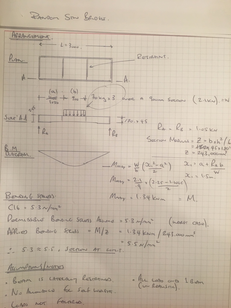
See below. The loading is fairly high and the assumptions fairly conservative.
I don't really know that much about structural timber, not sure what is done ref. load factors, I think there's something to do with load durations. (i.e. don't blame me if it collapses)
You have something that might look like an arch, in reality you have just weakened a bit of timber by cutting a bit out of the middle.
Increasing your 180mm beam depth, reducing your 3m span, load sharing between the beams, adding a decent handrail, not jumping up and down on it will all help. Make sure the depth of the beams are laterally restrained so they don't buckle.
I did the calcs for a mates build many years ago, using C16. The building control were more concerned with spans per section size & I remember them having a table, possibly from a BS standard.
My page of calcs from first principles phased them somewhat & they farmed it out to a consultant for checking. I found out later the consultant used a free program called Supabeam to check it.
Its pretty basic stuff though.
There was one beam that he’d doubled up that wouldn’t make the spec, so we used a 10mm thick steel plate between them.
Just to further muddy things, having seen the raw product and looked at the test procedure with our sawyer, variables are massive in the testing and continued supply, but to test every piece would leave you no timber as it would all be snapped. Wood can be from the same block, but growth patterns vary with wind edge, crowding, ground condition, topography, a ton of things. No two trees are the same. Pretty sure like most tested things, there is a pretty generous margin of error, so best round up some fatties to test the bridge 😉
The table further down the link from Flying Ox ^^ suggests that the beam centre dimensions will be key
Is it pressure treated? It should be really, and if it is I wouldn't be cutting a big slice out of it.
Just my reckon but I'd say 2 bits of 245 will be fine. Cutting down to 180 in the middle will be too weak especially if it starts to rot (see above)
<span style="color: #444444; background-color: #eeeeee;">I know keeping it straight will be more functional, but curves would make the bridge look so much better!</span>
An arch is only behaving like an arch if its in compression - cutting an arch shape out of something isn't achieving that.
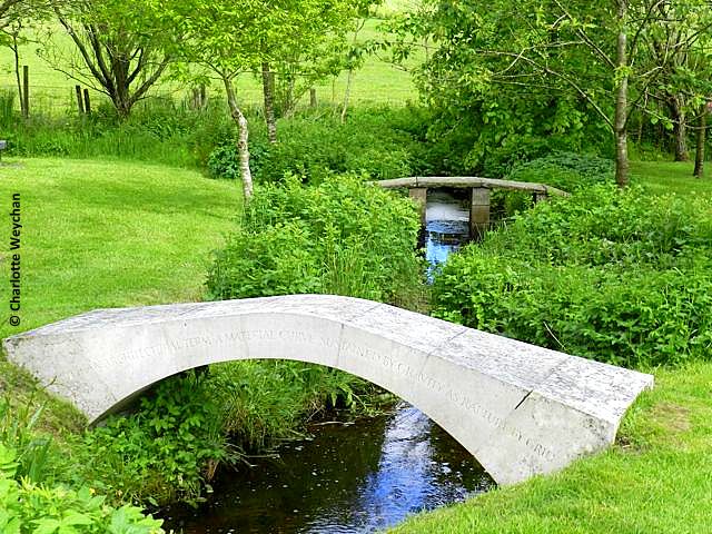
You'd be better off spanning the distance with suitable, straight un-cut timbers and clad the sides that with something you like the shape of. Perhaps add a nice little inscription like the one below 🙂
<span style="color: #545454; font-family: arial, sans-serif; font-size: small;">“</span><span style="color: #6a6a6a; font-family: arial, sans-serif;">Arch</span><span style="color: #545454; font-family: arial, sans-serif; font-size: small;">, n. an architectural term. A material curve sustained by gravity as rapture by </span><span style="color: #6a6a6a; font-family: arial, sans-serif;">grief"</span>
Part A of the building regs used to have span tables, you might be able to find an archive copy somewhere.
https://www.pathsforall.org.uk/pfa/creating-paths/sawn-timber-bridge.html
This may help. There are some links on the page that also may help. Perhaps it may be over the top given your span but some good principles.
Structural calculations for beams are more about buckling than stress. As you'll know, your 45 x 245 is much stronger with the 245 dimension vertical. When you put a load on it, it will try to twist onto the weaker dimension, and also try to move sideways in the middle to help it do that. So you need to brace the two together with some diagonals, and also brace them to each other to stay upright. You will only get the maximum bending capacity if you do that. It's called "effective length" if you want to look up more.
The question for me is what happens if it fails? Does anybody get hurt, fall in a pond, etc, or can they jump off onto grass? Timber design codes have big factors of safety because it's a variable material and (for things like floor joists) can have serious consequence if it fails. You might not need those factors. Timber always creaks and cracks before it collapses, so you can load test it before use to confirm that it's OK.
>The question for me is what happens if it fails?
Being STW, I assume there is a pond full of sharks with laser beams on their heads below the bridge.....
It's a 2ft deep pond. Big enough for some smaller shark species, but no great whites or hammerhead.
I've decided to keep the bottom flat but arch the top side either end down to 180mm. So a very shallow arc and there should be plenty strength in there.
It'll all be getting painted with exterior paint before being assembled.
Cheers
Just checked our calcs at work for a 3m span bridge - 300mm x 150mm Beams (x2) and 300mm x 150mm Cross Braces (x4) bolted with steel plates. Usually spec'd as Douglas Fir, which has good strength.
That's for Public Footpath specification.
You should be fine with what you've got for what you're using it for. As someone above said, put similar section braces across between the beams to stop them from twisting (and maybe put up a sign saying "Bridge only to be used by persons that can swim")
A little while ago there was a thread on here with someone who had a split purlin in the roof of their house; most answers were along the lines of "you'll be fine, strap it together, glue it, put a couple of bolts in it". You're building a decorative bridge in your garden and it's all *sucks breath between teeth* I wouldn't do that...
I don't get why people specify C16 when C24 has much greater capacity and is only pence more. We specify C24 for pretty much everything.
Also don't forget your handrail must be designed to take a horizontal loading of 0.25kN , which isn't a lot.
I'll put in at least two cross braces to stop the twisting, it's something I hadn't thought about before.