- This topic has 372 replies, 66 voices, and was last updated 13 years ago by RustyMac.
-
Lumicycle Halogen to LED conversion with piccies and a step by step guide.
-
BlackCatTechFree MemberPosted 14 years ago
I've finally received the new driver PCBs – the fab. that I use had a few problems so delivery slipped. I've done a basic 'systems test' and it works OK.
These have connections to allow both shutdown and half-power modes to be selected from a single-pole centre-off switch. There is also facility to fit a thermistor to reduce the current when the temperature rises – this isn't ideal as it slightly reduces the maximum output but should be useful.
I'm working on getting some heatsinks made and hope to offer an upgrade 'kit' of driver, switch and heatsink shortly.
BlackCatTechFree MemberPosted 14 years agoRight, guys, a bit of help is needed! The lumi-specific drivers have been ready for a while but I'm struggling to get heatsinks made. I was hoping to get some made at work but it seems that 'internal politics' (i.e. the turner trying to buy the place) has meant that isn't possible.
Can anyone recommend a good / cheap machine shop that does basic CNC stuff? I was intending to get these made professionally anyway but was hoping to get prototypes made at little / no cost just in case I ended up with a load of heatsinks that didn't fit…
VortexracingFull MemberPosted 14 years agoA place near me might help
mail me on eastham8ATaolDOTcom
and i can approach them and see what they can do.
can't promise owt, but i'll try.
some guys off here have lathes, maybe they could help?
stumpy01Full MemberPosted 13 years agoHELP!!
Having just resurrected this from the depths of the forum, I want to finally sort my conversion out this weekend but am a bit stuck.
From what I have read above, I was under the impression that I could use a single pole switch with on-off-on positions to set the light up to be low-off-high with a 200k resistor soldered into the 'A' control point on the driver board. Is this the case?
If it is, then can someone describe how I can do this as I don't understand what layout I need…..? A diagram would be great.I have also e-mailed Chucky(vortex racing) directly as well as Black Cat Tech who sells the drivers, but I thought I'd see if anyone was about on here who could give me some pointers.
I bought the 'B' type switch from Maplin:
http://www.maplin.co.uk/Module.aspx?ModuleNo=2341
in anticipation of it being possible, but might have to resort to the normal switch and just have on-off if I can't find out how to do it.
I'll need to get a new switch as the Lumi one appears to have stopped working after trying a 35W bulb one evening on a ride.nockmeisterFree MemberPosted 13 years agoHi Fella,
Nope on the old BlackCat drivers you needed TWO switches, one for on/off, the other for half power. I missed the update that Stephen(BCT) added, his latest driver is the future! er saying that it's not a big issue to flick 2 swithces 🙂nockmeisterFree MemberPosted 13 years agoPS…the conversion is WELL worth it!!
Oh I have a couple of new switches over that you can have for £2.50 posted!
stumpy01Full MemberPosted 13 years agoOh Poo!
I thought it was possible, from this on page 6 (posted by gray):
If using the standard Black Cat driver, then it's easy enough to use a SPDT switch such as the Type B Maplin one to have a configuration such as off-full-half (where the off mode is a soft off, so technically not quite as off as unplugging the power cable, but effectively the same), by using the control terminal and a resistor.
And Trout said on page 4:
there is also the option with a 3 pos switch to short direct the neg to A missing out the resistor as a soft off too
.
I must have misunderstood……
I think I'll just do it as full power/off. Gotta go into town on Sat for some shopping & there's a Maplin that I can get a new switch from. Thanks for the offer though.VortexracingFull MemberPosted 13 years agoback from work now, got your mail and will respond, but as the lads have said you can't have a on-off-1/2 setting with the old board.
I used the switch to switch from 1/2 to full and just pulled the lead out to switch off.
at this rate you might have it finished for summer solstice 😆
stumpy01Full MemberPosted 13 years agoHA HA!! At this rate I think you might be right. So long as it'd done by the 24/12, that's all I'm worried about.
Need to nab a soldering iron/solder from work for the weekend and should be able to get them sorted (so long as Maplin have the switch I need in stock!).
I ended up getting some heatsinks made, as I couldn't find any of those nitro car flywheel heatsinks on eBay (or anywhere else for that matter).
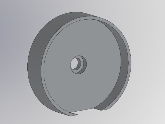
Can't remember the exact details, but it's about a 6mm back plate with a thin shell that comes forward to fit snugly against the Lumi can. Should provide a bit more surface area for heat dissipation. Looks like this: VortexracingFull MemberPosted 13 years ago
seems perfect. is the relief at the bottom to clear the nut in the case?
stumpy01Full MemberPosted 13 years agoYeah, the relief clears that flat edge in the bottom of the can (same as filing the flywheel down).
I had them made with a slightly oversize outside diameter so I could wet/dry them down to a really snug fit.
Either that image was saved before I finished the design or the angle makes it looks shallower, as in real life, the thin shell is pretty deep, and provides a decent contact area.I'll probably do some build pics (if I can persuade the other half to do the soldering this weekend) and pin my result to the end of this thread next week – perhaps with some garden beam shots too.
glenhFree MemberPosted 13 years agoI feel that I should point out that I've been running 2 sets of 3 x Cree XRE lumi halogen conversions for 2.5 years now.
They have no 'heatsink' at all, just the outer can, which is coupled to the led plate just by a snug fit around the edge with a bit of heat transfer compound.
I've had no heat problems in those 2.5 years and they still work as well as they did when I made them.
troutFree MemberPosted 13 years agoyes you can have off hi low with the old board and the switch stumpy has .
I just need to have a look at one of mine that does just that .
stumpy01Full MemberPosted 13 years agoAaaaaarrrrrrrrrrrrgggggggggghhhhh! Salvation!!
I would be extremely grateful if you could investigate how I can do this trout, bearing in mind that i am a complete numpty when it comes to electronics….!
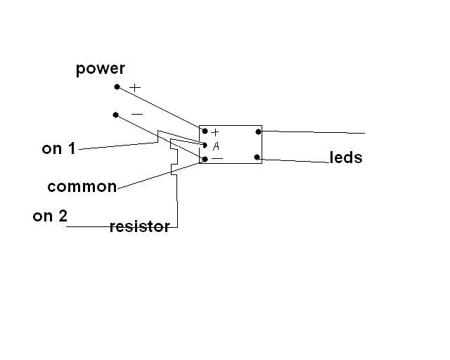
troutFree MemberPosted 13 years agoI hope I have this right .
both power connections as normalcommon on the switch to negative
one of the ons with the resistor to A this is the dim
the other on direct to A this one is the soft off
and with the switch totally off this is full power
Also soon there will be an even easier way to do the mod
stumpy01Full MemberPosted 13 years agoExcellent! Thanks for that!
Excuse me for being thick, but I take it that 'common' is middle position on the switch?
So, the switch as described above will be off at one extremity, on full in the mid position & the dimmed in the other extremity?
troutFree MemberPosted 13 years agoyes usually the centre terminal is the common one and the outers are the seperate on`s
so yes in the diagram up would be off
middle would be full power ( but technicaly the off position of the switch )
down would be dim
BlackCatTechFree MemberPosted 13 years agoSorry for being late to contribute to this.
Either version of the driver can have the three-mode function but you need a different switch. It is easier with the 'standard' version as you only need a single-pole, centre-off switch. The 'Dim Mode' needs a double-pole, centre-off and more complex wiring.
I'll put together a comprehensive guide to this tomorrow – bit late at the moment! However, Troutie's instructions for the standard version are spot-on.
BTW, Stumpy, your heatsink is pretty much exactly what I was looking to get done. I have managed to get one prototype made and will try and post a picture tomorrow also. I should be able to get a few done as a favour but if hundreds of people want them then I'll have to look at other options! Basically, the new driver sits inside the recess on the heatsink.
I'm also getting a prototype made of the LEDs and driver on the same board – currently looking at 3x XREs at 700mA as I doubt standard 2oz 0.8mm FR4 would handle any higher power than that!
As for using the LEDs without a heatsink, all I can say is NOOOOOOOOOOOOOO!!!!!!!!!!!!!!!!! I'm amazed this has worked at all! I have three Seoul P4s attached to an old PC processor heatsink 50mm x 60mm with fins and that gets too hot at 1A – certainly too warm to hold and at the point where you would be shortening the life of the LEDs. Without a heatsink they will get seriously hot and probably have a much reduced life.
(My setup does show the benefits of moving air cooling – with the fan on the heatsink is cool to the touch!)
stumpy01Full MemberPosted 13 years agoHoping to find some time later today to do this. Cheers for the 'common' clarification, trout.
BCT, I fiddled around with a few ideas on Solidworks & have a friend with some fairly decent machining capabilities. He's done me four to get started. I'm planning on converting one light for me & one for a mate, then if it works ok we're gonna do our other ones at some point. (Don't know if you are aware but the common Lumi set-up is two lamps – 1x20w + 1x12w).
I can e-mail u over the pdf of the drawing I did if u want next week? Only thing to note is that the outer diameter is slightly oversized so I could reduce it down to a tight fit once I'd tried it for fit. The LED board is also a snug fit as I wanted max contact.With regard to heatsinks in general – I wonder if a very snug fitting LED board allows enough transfer to the can on it's own?
BlackCatTechFree MemberPosted 13 years agoMy approach was a bit more simplistic! Drew a basic sketch and gave it to a friend at work and asked him to make that fit in this. (i.e. the lumi case)
I'd gauge that even if the heatsink board is a good fit you are still trying to transfer a lot of heat via not very much metal so the area under the LEDs themselves will still get very hot as the heat can't 'wick' away.
If you are always cycling then you may get away with it from the air flow but if you sit around with it on full then overheating is surely unavoidable. To be honest, I doubt the lumi case itself is a good enough heatsink when stationary when the LEDs are on full power.
Might be worth noting that unless they get *really* hot you aren't going to 'blow' the LEDs, but the higher the die temperature they run at, the shorter their life. A general rule is that under 60C you can get 50000 hours+. Many can take 120C but your life may be reduced to a few thousand hours. However, daft as it sounds but you may get slightly longer battery life this way as the Vf usually drops with increasing temperature.
The 'life' for LEDs by the way isn't until failure, they gradually drop light output and the life is quoted as when they drop to 2/3 initial output.
I wasn't aware that the common setup was two different power lights but I guess with the two power options with the LEDs then you can have both full power and have more power options.
BlackCatTechFree MemberPosted 13 years agoApologies if this doesn't work, just signed up to FlickR to put some photos online. (Virgin seem to have messed up the old NTL FTP settings so I can't get on to my webspace at the moment…)
Photos of the new driver and heatsink arrangement:
http://www.flickr.com/photos/50439158@N02/4631185669/
http://www.flickr.com/photos/50439158@N02/4631185715/I've tried to get maximum 'height' for the heatsink to allow maximum transfer to the case.
stumpy01Full MemberPosted 13 years agoThat looks like an ideal solution – nice & compact which is just what's needed.
Just realised I forgot to get any resistors so not gonna be able to do the conversion for a while – bu66er. More delay.
BlackCatTechFree MemberPosted 13 years agoThat was the aim! There were a few comments on the original conversion about the driver being hard to fit in and possible shorts so I thought it would work well to have it tucked away instead. The only issue I'm looking at is making sure there is no chance of it shorting against to back of the switch etc. When I am done testing I'll probably sell this as a complete kit with a new switch and socket pre-wired and including the heatsink so all people will need to supply is the LED board and lens.
The new version also has the resistor built in while still allowing shutdown so no problems like that! 🙂
troutFree MemberPosted 13 years agoSteven did you have a look for bits that would allow 1.5 amps drive current do they exist yet .
BlackCatTechFree MemberPosted 13 years agoHi Troutie, I've got some boards on the go at the moment that may allow me to do this. I'm using the Zetex ZXLD1320 which can do 1.5A. Trouble is that it is in a package which shall we say may be tricky to solder… (No pins, solder pads underneath and also stupidly fine pitch)
If that doesn't work out then there is a design out there to allow the ZXLD1360 to drive an external pass transistor to increase the current output. This will add to the cost and I think may reduce the efficiency. Otherwise, National do a few controller chips that are designed to work with external transistors but their solutions seem to have to be tailored closely to the intended supply and load while the Zetex drivers are much more flexible.
No immediate ETA on this I'm afraid – boards are due mid June but I'm being pestered to finish a reef aquarium lighting system ASAP so I'm finding it difficult to get other stuff done. (Thus the fact the new Lumi drivers are taking so long to get on sale….) If anyone fancies a bike light with 6 banks of 5 XPGs running from 24V then I may be able to help….
BlackCatTechFree MemberPosted 13 years agoJust to let you know that Diodes / Zetex have just announced a new chip, due in the next month or so, that does both 1.5A and proper thermal limiting, plus it comes in a package that doesn't need expensive automated equipment to solder. As soon as they become available through 'the usual suspects' I'll get some prototypes built up.
PaulBFree MemberPosted 13 years agoHi,
I have read through this and other threads and realise that developments are continually moving on, so could still do with some advice please.
I have two sets of halogen lumi's to convert, 13.2v 4 a/hr NiMH batteries.
Is the output of one can converted = to or better than a pair 20/12 halogens?
Triple or Quad XPG kit from Cutters (http://www.cutter.com.au/proddetail.php?prod=cut756), is this the way to go and all I need?
Any other suggestions?Cheers
Paul.
pdwFree MemberPosted 13 years agoI'm in the process of doing the conversion of a couple of halogens, and am getting some simple heatsinks made up as that RC part at the beginning of the thread seems to have been discontinued.
I can pretty easily get a few more cut. Anyone interested? It'll be nothing more than an aluminium disc 33mm diameter, 5mm thick.
I'd expect to have them in 1-2 weeks time, and would want £7 (inc P&P) to cover costs, hassle and the man-with-the-lathe's beer fund.
Email in profile if you're interested.
poisonspiderFree MemberPosted 13 years agoPaulB
I wouldn't advise a quad XPG with a 13.2V battery as you'll struggle to get a controller that will operate properly through the whole of the battery's discharge curve.
Check out the voltage requirements for both the maxflex and bFlex boards on Cutter's site for more info.
BlackCatTechFree MemberPosted 13 years agoI’ll try and give a simple explanation about battery voltage vs number of LEDs you can drive.
There are two basic ‘ways’ an LED driver works, Buck mode is where the output voltage is lower than the input voltage. Boost mode is where output is higher than input. In both modes where you have output close to input it causes the circuit problems. In essence, both types store charge in an inductor for part of a cycle and release it for the other part. Buck regulators would spend most of their time charging the inductor leading to overheating problems. Boost regulators would only need tiny blips of charge leading to control problems. (And poor efficiency)
There are devices know as Buck-Boost regulators which can bridge this gap but these are generally much more complicated circuits requiring more components and usually coming with an efficiency penalty.
If you were using 4 XPGs then your combined Vf would range somewhere between 12 and 14V (based on a single Vf of 3.0 to 3.5V) NiMHs can vary from about 1.4V fresh off charge to 1V or less when discharged. I’m assuming the 13.2V pack is 11 cells so 15.4V down to 11V or right across the Vf range of the LEDS.
Three XPGs would be 9 to 10.5V so if they were at the top end of the scale they would challenge many drivers with your batteries fully discharged. I can’t comment on other drivers but mine do keep working down to the point where Vin is just higher than Vf but generally at a reduced current. I wouldn’t advise this for extended periods though as it will be overloading the chip. However, as your voltage would generally be well above the LED Vf then you’d have no problems at all.
poisonspiderFree MemberPosted 13 years agoI don’t mean to be funny BlackCat but your ‘simple explanation’ is anything but, and I know what you’re on about. 😕
Bottom line is for a 13.2V NiMH: 4 XPG bad, 3 XPG okay
I run a 3 XPG Lumicycle conversion with a bFlex driver and a Hope 14.8V 2.4 Ahr Li-ion battery, it runs at full tilt (1A) for about 2.5 hrs. It’s a very capable helmet lamp.
jjllppFree MemberPosted 13 years agoBetter Alternative,HEALTHIER & just as GOOD. I Won’t look back
Guys you need to try these E-Cigs out rather than filling your blood stream and lungs with tar, arsenic and other nasty substances . . . Much Healthier, they don’t smell nasty and best of all you still get your nicotine fix!! 😀
NobeerinthefridgeFree MemberPosted 13 years agoBetter Alternative,HEALTHIER & just as GOOD. I Won’t look back
Guys you need to try these E-Cigs out rather than filling your blood stream and lungs with tar, arsenic and other nasty substances . . . Much Healthier, they don’t smell nasty and best of all you still get your nicotine fix!!
http://www.ecigarettedirect.co.uk/336.html
Posted 4 minutes ago #Eh?.
poisonspiderFree MemberPosted 13 years agoEr…thanks jjllpp you’ve lifted the debate a level with your insight into the ups and downs of home made LED lights.
(MODS this has to be an automated posting, surely) ❓
BlackCatTechFree MemberPosted 13 years agoYeah, OK, maybe not that clear after all! Difficult to explain why without getting a bit technical…
I suppose a general rule of thumb would be to multiply the number of LEDs by 4 and if this is less than your battery voltage you are fine, otherwise I think you’ve going to need a bigger, erm, battery…
There are ways around this limitation but they’ll cost ya.
That any clearer? 😉
snapsFree MemberPosted 13 years agoDoesn’t the chip just go out of regulation & the LEDs gradually dim as the battery voltage drops towards vf times 4?
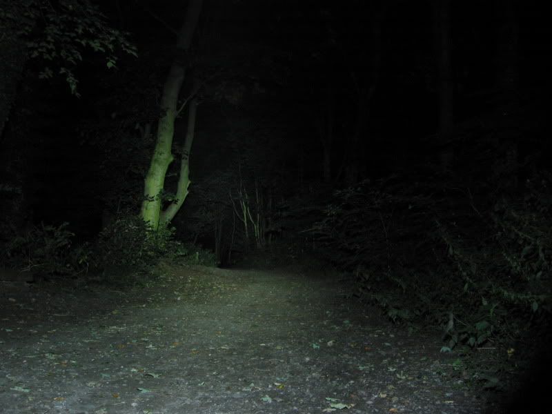
troutFree MemberPosted 13 years agoHe up Steven any update on the 1.5 amp driver
you mentioned earlier .here is a beamshot from a single XPG led driven at 1.5 amps .
a theretical lumen count of 460 lumens from one ledstueyFree MemberPosted 13 years ago1.5 amps, is that allowed !
–
Troutie are these a newer breed XPG?BlackCatTechFree MemberPosted 13 years agoYou are right, it does generally just go out of regulation but there is more to it than that.
For starters, the Vf of an LED is not a constant. XPGs are good but variation between LEDs and over temperature and input current can mean the Vf per LED can rise to 3.5V or more which means up to 14V with 4 in series.
I’ve spent ages trying to make the following bit clear with some technical stuff but I can’t…
When the battery voltage is low, the chip gets hotter than when it is high. This can shorten the life of the chip or even cause it to melt and go up in flames. (Well, maybe not that drastic but you know what I mean!)
The topic ‘Lumicycle Halogen to LED conversion with piccies and a step by step guide.’ is closed to new replies.