- This topic has 1,254 replies, 94 voices, and was last updated 12 years ago by stevemorg2.
-
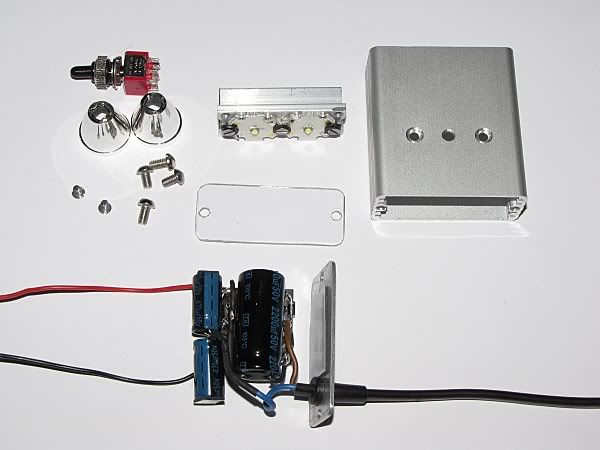
DIy 700 lumen batteries inside light
-
bobblehatFree MemberPosted 13 years ago
NaaaaaaaaaaaaH! BCT beat me! 😥
(p.s. … thanks for the info Stephen)
troutFree MemberPosted 13 years agoWhoo Whoo
that 2 Troutie threads to go over the 1000 mark
is that a STW recordbobblehatFree MemberPosted 13 years agoWell done Troutie …..and so worthy of it’s high post count too. Still pulling in new builders!
As a new boy on the block …. what was the 1st 1000+ thread? I can’t find a way of sorting or searching by post count.
I’m half way through my dynamo version build …. anyone else done one yet?
 troutFree MemberPosted 13 years ago
Dont know about the dynamo version but quite a few on here may be interested as have had a few enquiries for dyno lights .
my other big thread
http://www.singletrackworld.com/forum/topic/trouties-new-light-is-on-the-way-update-to-all-interested-folks-who-emailed-meBlackCatTechFree MemberPosted 13 years agoWhat is the output range of a typical dynamo and what sort of power can they put out? You can get very high capacity ‘supercaps’ but they are usually 5.5V maximum and fairly low current output capability. Of course you can put two in series to get 10V but you’d then only get half the capacity, still using something like 1F ones you’d have 0.5F so far more than your 2200uF one.
I’m guessing that you only need a fairly low output running from the storage capacitor? Should be possible to have it sensing when the power input stops and have it switch down to a much lower power to give decent run-time.
That said, I’m messing with supercaps for carriage lighting on model railways and they only last a few minutes there once power is removed and that is only pushing a few mA through 5 or 6 standard LEDs.
bobblehatFree MemberPosted 13 years agoThanks Troutie. Do you think I should start a new topic, so as not to clutter up this one with Dynamospeak? I’m happy to stay here or go for a new one, as I think it only fair to ask as you are the OP.
I’ll wait for a reply before answering BCT either here or on a new topic.
troutFree MemberPosted 13 years agoI would say keep it here so easy to find all the other bits .
and I am curious too .and boosts the post count 😉
bobblehatFree MemberPosted 13 years agoThanks again Troutie …. appreciate it!
BCT – I’m going for a simple circuit at first …. with no attempt to have any sort of standlight function (your query seemed to suggest that it might have). I intend to run blinkies as well, front and rear, the front acting as back-up when switched to steady …. and as a work light if needed. If all goes well, I might add a rear dynamo driven light later.
The 2200uF is across both leds and is for smoothing purposes only, it reduces flicker at low speed.
I’ll provide links lower down for those who are interested, but the main inspiration for the circuit is Martin’s excellent website and a couple of CPF threads from Znomit and Ktronic …… well worth a read.
Basically, you can get over 500mA at varying voltage from modern dynamos, and the beauty is that it’s like a constant current source. At normal speeds you can rectify the output of the dynamo and feed it to the leds. As you all know … you can get a lot of lumens out of a couple of xp-g’s at 500mA. The basic stated output is 6V @ 500mA i.e. 3W ….. but don’t let that fool you …. there’s far more to it than that. If I remember correctly, Znomit or Ktronic got around 11W out.
Now, using Martin’s Circuit number 7, and Ktronic and Znomit’s experiments, you can boost this output to up to nearly 1 amp ….. all with simple passive components. That’s what I am building.
Have a read here for some excellent facts and circuits.
and here …..
and here for …..
BlackCatTechFree MemberPosted 13 years agoReading all that makes me think I need to read up on how dynamos work! Forgotten they were AC to be honest, caps make more sense then but why 50V? They are far smaller in lower voltages.
I’d assumed you were storing some of the output to keep the light going when you stopped cycling and to keep the output up when you slowed down.
(Anyone do hybrid bike lights by the way? Although I guess your rear wheel locking up when you brake may be a big difficult to get used to)
Wonder if anyone has tried 2x XPG in inverse parallel from a dynamo. You’d save on the losses through the bridge then. Only problem could be flicker, you’d have to add two diodes and two capacitors to avoid that if it was a problem.
A fairly simple way to add low-power head and tail lights from this circuit would be to charge a supercap via a zener then attach your LEDs to that. I’ve been messing with charging supercaps using On Semi NCP45xxx LED drivers, these put a constant current in to the cap rather than being limited using a resistor. Use a zener across the cap to regulate the voltage. Rapid do a flasher IC that I use in various products I sell on eBay which could be used for the flash mode, a switch to bypass it would be an option for steady head lights. I’m actually doing something like this on a batch of PCBs I’ve just put on order.
I think I’ve read somewhere about maximising power out of a dynamo by electronic means, will have a look up when I get the chance. The passive approach is simple but it seems to be difficult to optimise for the best combination of output power vs speed.
bobblehatFree MemberPosted 13 years agoYou’re pushing the boundaries of my knowledge (and memory 😳 ) here Stephen!
I think the high temp (105C) high value caps recommended are only available in relatively high volt versions from Maplin (my easiest source) and I’m sure I read somewhere in a related thread (maybe not the 3 pages I mentioned) that the higher voltage versions have better ac ripple somethingorother and prove more reliable than lower voltage versions. Does that make sense?
You can use any value smoothing cap you like, the larger the more smoothing it does at low speed, but requires a few more turns of the wheel before you get any light out, compared with lower value ones. Usually, this is not a problem.
The two electrolytics that make up (replace) the bipolar need to be high voltage too, I think …… apparently they warm up. To quote from Martin ….
Using low-ESR parts, high DC voltage rating (470uF 63V, 220uF 100V, 100uF 160V as a guideline), high temperature rating (125 degC) is the way to go. If the caps heat up noticeably, something is not right (and precious energy is being wasted). I’d stay away from using underrated caps with active cooling.
One other thing to note. If your leds get accidently disconnected from the circuit, your dynamo can generate quite high voltage on an open circuit and is stored nicely in the smoothing cap …… ouch! So Martin strongly advises that you keep the smoothing cap very well connected to the leds and physically near the leds … in the same housing and mechanically secure. You can switch off the dynamo output with no problem to provide an on/off function for hub dynamos …. just put a switch before your light circuit. (Bottle tyre driven dynamos don’t need one because you can disengage the bottle from the tyre!)
Znomit recommends this circuit for a standlight function.
I think this is all tried and tested stuff …. so that’s what I’ll go for on the first build.
I can post up a schematic and circuit diagram with component values if there is enough interest … but I’m only borrowing from the great work done elsewhere!
p.s. I’m using an older shimano NX-30 hub dynamo on a mavic hoop, attached to my old apollo hack bike that I take to college ….. not something that has a high “steal me” factor! So this light will bolt permanently (I hope!) on that bike! Yep! The mavic rim and dynohub is worth more than the rest of the bike! 😆
Jammy111Free MemberPosted 13 years agowow i cant believe i haven’t seen this thread before. Im really interested in making one. Am i right in thinking what you need it the kits from troutie and BCT, one of the boxes from maplin and then someway of powering the thing?
Are troutie and BCT still doing the kits for people, if not is it possible to source the parts from elsewhere?
I was previously thinking of buying from DX but this looks like it will be better, am i correct?
Is there a step-by-step guide for building it anywhere as i’m a bit of a novice when it comes to electronics but would like to learn.
Any advice is greatly appreciated, and sorry for being a numpty. (if you dont want to clog up the thread you can email me direct at jammy111@gmail.com)
BlackCatTechFree MemberPosted 13 years agoLooking at low ESR caps in Rapid, 1000uF 10V is about twice the ESR of 1000uF 50V so you would get higher losses with the lower voltage cap. Much small physically though so you could use a higher value capacitor. 50V 1000uF is 16 x 31.5mm and 32mR. 10V 3300uF is 12.5 x 35 and 28mR.
I see the point about potential for damage if the LEDs go open circuit – this is quite a common issue, especially for boost drivers. I’d suggest connecting a tranzorb across the dynamo output to clamp overvoltages as an extra layer of protection.
It would be interesting to compare an inductive LED driver with the capacitive solution – inductors are usually better at storing charge but for driving more than one LED you’d need a boost driver. Worse, for two you’d likely need a buck-boost.
LoveTubsFree MemberPosted 13 years agoFlicker, nice job 🙂 Was the power lead included in the Trout-kit, or a Maplins job?
Cheers.
bobblehatFree MemberPosted 13 years agoHi Jammy … Yep 1 kit from Troutie, 1 Kit from BCT, case from Maplin (or elsewhere) and a battery and lead. Troutie and BCT reported kits available a page or two back …. so should be no prob.
Depends what you wanted to buy from DX ….. but if you take the bastid light (to quote Troutie!) as a comparison …. see here – page 14 ….. there are better P7 lights though. This light build is renowned for its good throw and good output … so if that’s what you need …… ?
Apart from Troutie’s initial few pages showing the battery inside build which will get you going, there is Citizen Kane’s photo build on page 13 which is very good … and other bits of info in the rest of the 1000+ posts ( He! He! 😈 )
bobblehatFree MemberPosted 13 years agoBCT – thanks for the info.
I think you are operating a couple of levels above my electronic knowledge …. but I always look forward to seeing alternatives!
bobblehatFree MemberPosted 13 years agoTroutie … Just finished reading your other big thread … wow!
Darn glad certain characters haven’t posted on this one ….. Jeez!
troutFree MemberPosted 13 years agoHa Ha I hope ypu had a beer or two whilst reading it .
Yes it had its moments but it did help develop the Liberators .OK finaly got hold of a bastid sent in for repair whilst i did have one of the first to disect it would nhave been not right to use those beam shots .
so got to go to my beamshot woods now some of the snow has gone
some comparison shots now
Magic shine all shots on high .
Hammond CK like the ones we have all been building on here
now the cuboid I built with 4 Reginas and XPGs running at 1.5 amps
paper lumens 1800 .finaly a liberator mk3 with a measured 1700 lumens .
Slide show
bobblehatFree MemberPosted 13 years agoBrilliant Troutie …… just what I wanted to see! Bet Jammy will like it too!
That’s made my mind up on something I’ve been pondering! Should I make an adjustable mount for my twin Hammond CK lights (high beam and dip beam) ….. Yep! I’d almost have a Cuboid (but at 970mA) if I could realign the dip beam upwards to match the high beam, for those special occasions! 😈
Jammy111Free MemberPosted 13 years agocheers for the advice bobbiehat, ive sent troutie and BCT and email to see if they have any kits left. Does anyone have any advice on a battery solution?
I was going to buy one of the magic shine lights with the external battery pack but much prefer the sound of making my own for a similar price. Is there a rechargable external battery like this available? Also where do the bar mounts come from?
Sorry for all the questions but i’ve read through the posts and cant find any answers,
J
bobblehatFree MemberPosted 13 years agoBattery depends on your wanted runtimes! Anything from my cheapy 8x Eneloop AA’s (or even cheaper “GOOD TO GO’s”) … to SubC NiMH packs …. to 18650’s. Got any AA NiMH’s laying around the house ….. just to try it before spending big(ger) money? Get an 8 cell AA holder from Maplin … cheap starter.
If in UK and you want the good stuff, not cheapy magicshine stuff …. mtb batteries are recommended …. here
Troutie supplies the mount in the kit … I think you just find an O-ring of the right size …. dig back through the thread … you’ll find it.
p.s. You should get around 2.5 hours on full out of 8 AA eneloops/Good-to-go’s … I got exactly that, running 2 lights together at 1/2 power.
Jammy111Free MemberPosted 13 years agoBattery depends on your wanted runtimes! Anything from my cheapy 8x Eneloop AA’s (or even cheaper “GOOD TO GO’s”) … to SubC NiMH packs …. to 18650’s. Got any AA NiMH’s laying around the house ….. just to try it before spending big(ger) money? Get an 8 cell AA holder from Maplin … cheap starter
That is gibberish to me 😀
I think what you are saying is I can link up some cheap AA’s or buy a more expensive battery pack thing from mb batteries?
About 2.5 hours on full would be fine for my needs, so I presume I can get away with some AA’s linked up somehow. Ill have a scout around on maplin and see what I can find..
EDIT: I found this, so 8 rechargeable AA’s whacked in there would do the trick? How do i then connect said ‘battery pack’ to the light? Also how easy are these to weatherproof?
thesurfbusFree MemberPosted 13 years agoTroutie – I am in the middle of building a battery inside light (my 3rd hammond light), but still waiting on the XPG’s I ordered from you on the 17th November, are you still waiting for the Reginas? or more than likely my order is stuck in a snow drift.
flickerFree MemberPosted 13 years agoLove tubs….thanks, I’m pleased with how the lamp finished up. The lead I used is a magicshine extension lead, approx. £6 off eBay. Chooped it up and fitted one end to the lamp and the other to the battery.
Jammy111….you can go for pretty much any battery you want, as long as it supplies more than 8v (if you’re using 2xXPG) and less than 24v. I’m still undecided on what to use (I’ve currently got a 10S1P 18670 12v 4000maH NimH pack duct taped to my stem, weighs in at a chunky 650g 😀 ). I’m either going to go for a 4S1P 18650 14.8v 2400maH LiIon pack (approx. 200g to 250g) or possibly a 3S1P 11.1v 2200maH LiPo pack (approx. 175g).
I’d originally ruled out the LiPo option, as I was concerned about running the packs too low whilst I’m out, but I’ve found a little module that plugs into the balance port and sounds an alarm when the cell/cells drop to a preset level (user configurable). A decent balance charger is about £25, warning sounder was £6 ish and a Zippy flightmax battery £12-£13 ish. It’ll be cheaper to go for the LiIon, but not by a great deal. Decisions decisions…..
Jammy111Free MemberPosted 13 years agodecided to go for the 18650’s and bought a 3 battery holder from BCT with all the other gubbins. Next step is getting some batteries and a charger, any recommendations?
bigjimFull MemberPosted 13 years agoI ordered batteries from DX, but expect a 6 week wait or more at this time of year. mtbbatteries do sell them but more expensive, you pays your moneys etc.
johnfbFree MemberPosted 13 years agoProbably mentioned elsewhere on this thread but the other power option is to salvage some 18650s from old laptop batteries. I pick the odd one out of the recycle bins at work. You could maybe ask at the local dump if they’ve collected any? Often there’s only one or two cells out of the six inside a pack that have failed so you can drop them into one of BCT’s holders.
Here’s some links I found handy
You’ll need a multimeter to test, and they’ll be unprotected so you’ll have to watch out not to discharge to death. Even if you do though, they were gratis in the first place.
troutFree MemberPosted 13 years agoTSB
Will have a trawl through the mail as I dont recall your order
Jammy111Free MemberPosted 13 years agoright then, its time for more questions 🙂
I found some batteries which should fit the bill and are pretty darn cheap:HERE
I’ve asked BCT to include one of his 3 cell holders with my order and I was wondering if it was possible to charge all of the batteries from one device whilst still connected to the holder. The reason for asking this is I was thinking of trying to weather proof the holder/batteries with maybe some shrink wrap…
Are there any other novel ideas out there for weatherproofing that I am unaware of?Lastly how do I go about connecting the batter holder to the light box?
In return for all of these questions I think i will write a bit of a walkthrough/step-by-step guide for morons (like myself) which I think should be quite a valuable resource.
Cheers,
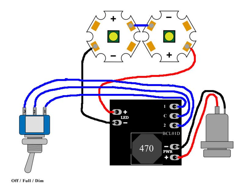
JMountainKingFree MemberPosted 13 years agoGiven that BCT is now supplying the new style driver and its been a while since I did A level Physics can someone who knows more just check the wiring diagram below to see if I have things correct.
thesurfbusFree MemberPosted 13 years agoI bought these Batteries they will sell them for £7.50 the pair posted, UK as well.
Jammy111Free MemberPosted 13 years agocheers TSB ill give those a go instead! An extra hour runtime or so.
I’ve been doing yet more reading and it looks like a water bottle method of housing the battery is going to be best/easiest. Should just be a case of waterproofing the cable exit through the mouthpiece and then packing the batteries in with something to stop them rattling around aka foam or bubblewrap.
Can i double check it is the 1455C802 hammond box that I need i.e. the small one with the plastic end caps.
Jammy111Free MemberPosted 13 years agoFor anyone interested in buying batteries the the ebay seller that TSB linked me to accepted an offer of £12 posted for 3x 18650 3000mAh 3.7V protected cells which seems like a bit of a bargain!!
norcbotFree MemberPosted 13 years agoI think im going to have another go but make it with the batteries inside. May go with the bigger hammond box to get in more than batts though. Time to get some more LED’s and stuff. Trout and BCT YGM.
defaultslipperFree MemberPosted 13 years agoHi Trout- light was working perfectly until i decided to try and play with the LEDs with the battery still connected. Think I have blown one of the LEDs. Could you let me know how much a replacement would be to post out? Think I might be able to salvage the optic (it’s only attached with the sealant).
Lesson learned- if it ain’t broke don’t fix it!BlackCatTechFree MemberPosted 13 years agoApologies to Troutie for a slight thread-hijack here but I’m after some advice from the DIY brigade.
I’m looking at the possibilities of designing a driver with microcontroller built in but I’m not sure just what is needed and what is a pointless extra. The basic spec will be 1.5A output, control from a push-button, thermal limiting and battery monitoring. I’m also intending to have reverse input protection and a PC interface as an ‘extra’ to make setting up easier.
Are there any suggestions for other things to add?
What input voltage range is desirable? Would, for example, 20V be sufficient or is 24V a must-have? (20V would simplify quite a few things and allow performance improvements)
What is the preferred shape / size? I’ve been considering a 1″ circle similar to the bflex but this is making things awkward. Rectangular boards are much easier to lay out so would there be any major problems with going that way and if so what maximum sizes could people live with?
I’m looking at two versions, one a boost reg, one buck. It may be possible to scale the buck reg up to higher currents at a later stage, the boost is probably limited to 1.5A for most applications.
Reduced current modes will of course be present but I’m wondering if anyone knows if the bflex-type drivers actually reduce the current or just pulse full-current at a limited duty cycle. My idea was to have a 1.5A limit and for say 350mA to limit the duty cycle to 23%. The problem is if you are using it with a 1.5A capable LED this is no problem but lower current LEDs often can’t take such high currents even as short pulses so although the mean current is OK the peaks are too high. Actually reducing the current is a PITA though but if necessary can be done.
Bear in mind that I’m only considering hardware capabilities here – this is going to be a collaboration with the software being designed by someone else. (I’ll let that person add their own stuff if they want to, won’t mention names at this point as I’ve not asked if it is OK to)
troutFree MemberPosted 13 years agoNo Worries at all if it means we get some good stuff to play with .
20 volts is a bit limiting as it falls just outside a 5 cell Li Ion
so 24 would be better .as quite a few folks use 18 volt drill batteries which come of the charger at 21 volts .With the XM-L`s coming along then 2 amps or even 3 amps would be desirable .
All the Taskled drivers Bflex Maxflex ect are true constant current drivers and lower the drive current for dimming
no pwm in them . there seems to be an aversion to pwm drivers in the diy mob
Single sided is easier to mount in a case .
re the modes then there may be trouble ahead .
one mans ideal mode ie hi med low is not ideal for the next man .
but if you have the memory to put in a few differing modes then great .
size as small as poss but probably rectangle not square
MountainKingFree MemberPosted 13 years agoTrout are you able to confirm you received payment OK for my order?
Just want to be sure as have had a few problems with local post recently.
BCT your bits arrived yesterday, many thanks. If you get a moment could you check the wiring diagram I posted a few posts back and make sure I understand the new driver wiring.
Thanks
Paul
troutFree MemberPosted 13 years agohi Paul
posted yesterday first class so you should have had it today
but I guess the PO is pretty busy
Troutie
BlackCatTechFree MemberPosted 13 years agoMK – diagram looks fine, just check the polarity of your power socket. You are showing it as barrel negative, lumicycle packs are barrel positive. (I don’t know what battery you are using though, it is likely it is correct, just thought I’d best point this out for completeness)
Troutie – ok, 24V it is then. Main hassle is finding PFETs that can take more than 20V on the gate – this is the reverse voltage protection. They are out there but are expensive compared to lower voltage ones. (Hmm… Wonder if I can use a Zener to clamp the gate voltage…)
I’ll look in to reduced current modes, the older Zetex drivers could be made to do this by PWMing at a very high rate – they ended up integrating the PWM waveform to produce an analogue voltage. The new driver has a dedicated PWM input so I’d need to check if the same effect could be achieved. The boost driver will be OK, this uses analogue dimming anyway. While it goes away from the ‘one size fits all’ approach I could supply them in various ‘maximum output’ grades as per my existing drivers.
I wonder how well the bflex regulates at the lower currents – working back from the components they seem to use it appears they are optimised for higher currents. 350mA for example needs a higher value inductor to get good regulation – in general the higher the current the lower the inductor value.
The buck driver will use a controller which drives an external FET. The current limit is mainly set by this FET but also by the current carrying capacity of the inductor. To use an inductor with a high enough value to work at 24V 350mA as well as 12V 3A I’d need to go for a very big package. It may be that I do a 1.5A version with full analogue reduction and a separate 3A version that needs to PWM for significantly lower currents. You’re only going to buy the 3A version if your LEDs can take it so that shouldn’t be an issue.
As for the modes, that won’t be my area as while I can do software I never seem able to find the time. I’d imagine a few basic modes would be built in and then anything more complex could be set up via the USB interface. I’ve never used a bflex but reading the manual it seems it must take a while to set it up properly. If we can do something where the basics can be set up fairly easily from the switch and anything more complex can be done easily from a GUI then that should be a good solution.


The topic ‘DIy 700 lumen batteries inside light’ is closed to new replies.