- This topic has 113 replies, 16 voices, and was last updated 8 years ago by tragically1969.
-
Digi Phase Converters, 3 phase motors etc, Anyone?
-
jamiesiloFree MemberPosted 8 years ago
hope somebody can help me with this, otherwise i’ll be driven to asking on one of those electronics geeks forums…
i bought a digital 1ph 220V to 3ph 220V converter on ebay to run a dual voltage motor, ie one that can does 380v or 220v .
got it all hooked up in the end after a very chinglish instruction manual and the motor spins up to speed ok, or seems to, but is completely lacking power. attachign the drive belt to it causes it to stop almost completely.
voltage between phase reads about 80V, which is right yeh? a third of 220ish?
but output voltage on the digi thing says 36 volts or so.
max voltage is setable and is set right to 220.there we go anyway. i can’t fathom it. any help would be great.
UrbanHikerFree MemberPosted 8 years agoCould be wrong, but line to line voltage (ie between phases) should be higher than line neutral? But probably depends what you’re measuring it with.
ChristianFree MemberPosted 8 years agoWhen im testing 415v 3phase, each leg to the winding is 220v to earth and between the windings is 415v, what have you got to earth from the motor terminal?
jamiesiloFree MemberPosted 8 years agoah ok, i’ll check some things.
it’s wired in delta so there’s no neutralso at 220v 3 ph what should it be between phase and earth christian? any idea?
dvatcmarkFree MemberPosted 8 years agoLine to line voltage is about 1.7 times the line to neutral voltage.
Its worth noting that a digital volt meter wont read correctly as the voltage waveform will not be sinusoidal. If you want to measure the true output voltage you’ll need a oscilloscope I’m afraid.
Can you give me a link to the manual for the unit to have a look at?
igmFull MemberPosted 8 years agoWhen im testing 415v 3phase, each leg to the winding is 220v to earth and between the windings is 415v, what have you got to earth from the motor terminal?
415V 3ph = 240V ph-earth I hope
400V >> 230V and so onsquare root of 3 being around 1.73 and all
ChristianFree MemberPosted 8 years ago220v three phase should show 220v between phases, as 415 shows 415 between phases, to earth probably 120v. dont work on 220v three phase myself but principle is the same. seems like the output to the motor is low as the unit is telling you which is why it has no torque, surpised its turning at all if thats the case mate!
dvatcmarkFree MemberPosted 8 years agoNot quite, the 220v is line to neutral I.e. star connection so if you could measure the voltage across the outputs you should see 380v. But a mentioned above you can’t do this without a scope (the output is a square wave, so a standard RMS algorithm like virtually all multimeters use doesnt work)
My initial guess is that the inverter is current limiting its output.
jamiesiloFree MemberPosted 8 years agook great, thanks a lot everyone.
yes i figured it was low volts to motor giving low torque.
still haven’t checked voltages cos i’m lurgied up but will do with an needle type meter if that worksdvatcmark, it’s this one :
http://www.ebay.co.uk/itm/251389853828
quite q lot of info there within the listing.
i notice it says “single phase connected to any 2 phases” under How to install this VFD
i’ve got live and neutral of supply just to one terminal each at R-S-T in diagram. should i try bridging 2 together from live? guess i should.ChristianFree MemberPosted 8 years agoYou can have 220v phase to phase, not just 220v to neutral bud, equalling 380 to 415v, like i said not something ive worked on but does crop up!
dvatcmarkFree MemberPosted 8 years agoLooks like a nice little unit. There isn’t much you can wire wrong really, just connect the single phase input between any two of r s and t and the motor across u v w, the link the motor to be star or delta as required.
Don’t get hooked up on the voltages, as its current and frequency that drives motors not volts.
As its giving an output and turning the motor its unlikely to be knackered, so I would put money on it being setup wrong.
The unit has a variable output either from an external input (variable resistor) or using the keypad. In the settings I’d check this first so that a) the output is set it to be by the keypad and b) the output is set it to 100% from the keypad Also check the max output frequency is set to 50hz .
Inverters usually ask for a motor size too to limit the current to a safe value to protect the motor. This might be set too low so check that too.
If the manual is chinglish this might take some time I’m afraid.
dvatcmarkFree MemberPosted 8 years agoYou can have 220v phase to phase, not just 220v to neutral bud, equalling 380 to 415v, like i said not something ive worked on but does crop up
220 to neutral is 380 line to line just like the spec says.
TheBrickFree MemberPosted 8 years agoVfd usually have a voltage vs frequency curve. You will only get the 220 v phase to phase at 50hz (or 60 hz in N.America) do you have it at full speed?
jamiesiloFree MemberPosted 8 years agothanks dvatmark,
yep all that’s checked and good. not getting hung up on volts, just that the voltage is the only setting that’s wrong that’s all. and aye, i don’t have the supply phase connected accross 2 of RST so that should sort it.
and i know the motor’s not knackered. it has to me my wiring or a setting, and seeing as i’ve sorted all the settings, it’s user error, as usual.
right, might go off and change that wiring…TheBrickFree MemberPosted 8 years agoP.s. 220 v three phase exists I north America. At work we have installed a mchaine with 480 and 220 three phase systems
jamiesiloFree MemberPosted 8 years agothat’s right, and this is a 380v in y wiring or22o in delta wiring 3phase motor, made for france. they did this so partly so they could sell to america withotu any parts changes
funkynickFull MemberPosted 8 years agoLooking at the ebay page it’s definitely a 220V line-line output voltage and not a 415V, so do make sure that is the kind of motor that you have, otherwise you are going to be in trouble getting it to run at the full rated speed.
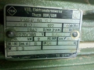
Now, talking of the motor, do you have the name plate ratings? And is there anywhere in the inverter settings pages where you can enter these values? Most importantly, the rated voltage and rated speed, and also likely to be the pole number of the motor if you want any idea of how fast you are actually trying to spin the motor!
My guess is that same as a couple of folks above, that the voltage/frequency settings are wrong, and so it’s trying to run the motor with too little voltage for a given speed.
jamiesiloFree MemberPosted 8 years agothanks nick and again dvatcmark.
as i said, the motor is dual voltage, ie it’s designed to run ate 380v y-shape wiring, or 220v delta wiring. that’s why the converter i bought is 220v 3ph out, to go with the delta option, right?
i have of course used the motor plate to get the relevant ratings and entered them in the inverter settings: max voltage, frequency, speed rpm etc. pole number i couldn’t find, though am under the impression it’s usually 4, and the inverter factory setting is 4
brFree MemberPosted 8 years agoNot sure if it is relevant but when I looked at a 3-phase saw my (electrician) son mentioned something about needing a 3-phase supply to the house – or the ‘ability’ to get 3-phase from the local electricity sub.
At this point I switched off and looked only at 240v :-), so it could be duff info.
jamiesiloFree MemberPosted 8 years agonope it’s definately wired delta twonks. and as far as i understand, in this case delta is for 220v, star, or’Y’, is for 380v
just tried bridging the supply phase to the inverter over 2 of the RST terminals as described on ebay listing. made no difference whatsoever.
now i’m really stumped…
jamiesiloFree MemberPosted 8 years agomy next line of enquiry is setting ‘intermediate frequency/voltage’
these values used to define start-up curve. from readin manual again it sounds like i may need to increase one or the other to get more torque as it’s starting up. off to have a go…jamiesiloFree MemberPosted 8 years agoright, so i can now get motor started while connected to the saw and runs up to speed, (though i must admit it seems very fast. rpm is set in inverter according to motor plate though)
i changed the intermediate voltage, ie the curve of the start-up (graph V against F) because in the manual it said wrong setting may result in under-torque of motor.
however it still seems lacking power/torque. and goes very fast as i said. i’d be worried about belts, and whole machine vibrates unsettlingly.
any more thoughts?
funkynickFull MemberPosted 8 years agoJamie..
Can you post the name plate numbers? From those it should be possible to work out what pole number the machine is.
From what you are saying, it does sound like it could be a 2-pole machine, and not a 4 pole.
mcFree MemberPosted 8 years agoBefore you start playing with the more advanced settings, go back over the basics.
Single phase should be across any two of the 3 input terminals. What ones doesn’t matter, as they all go through rectifiers to provide a DC supply that is then used to generate the 3 phase. The inverter is only interested in seeing 280+VDC in it’s capacitor bank.
What does the motor name plate state?
When wired in Delta, you should be using the higher of the two current ratings on the plate.With the motor running, what frequency is shown on the drive? Provided it’s saying 50Hz, the motor should be running at the correct speed (that’s provided the motor plate is rated for 50Hz mains supply).
Also check to see how much current is being output (Hz, V and Current are all selectable for the display), and look to see what it maxs out at when you apply a bit load.tragically1969Free MemberPosted 8 years agoWhat’s the motor driving ?
Sounds like you have the drive in the wrong mode, needs to be constant torque, it may be in V/F at the moment which will limit torque at low frequency (assuming you have a ramp accelerate program set in it)
Edit: Ignore all that, just read its a saw you are driving
Check and double check parameters !!
jamiesiloFree MemberPosted 8 years agoright, here we go

mc, yes single phase is over 2 of RST. dc voltage reading 300 odd.
plate suggests 220v = delta and will draw 5.9A current.
according to inverter display it was drawing about this til it got up to speed, then went down to 2.9 or thereaboutswith motor running 50 Hz shown on drive
funkynick. any clues there if it’s 2-pole or 4 pole?
jamiesiloFree MemberPosted 8 years agothanks tragically1969. it’s actually running a combinaton machine ie saw, spindle moulder, planer/thicknesser. quite a small one though.
anyone know what the cos and symbol spec is above the weight on plate?
tragically1969Free MemberPosted 8 years agoPower factor.
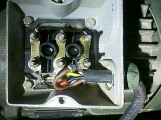
Can you post a picture of the terminal box wiring ?
jamiesiloFree MemberPosted 8 years agoyes
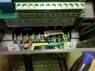
the bit of red on the black wire is just an old bit of sheathing or something.and here’s one of the box drive connections for good measure
all looks right, right?
RustyMacFull MemberPosted 8 years agolooking at the drawing on the Ebay page it may be a switched output, have you checked it is set up to output to voltage you require?
I’m looking at the KA,KB & FC, FA & FB switch set up.
tragically1969Free MemberPosted 8 years agolooking at the drawing on the Ebay page it may be a switched output, have you checked it is set up to output to voltage you require?
I’m looking at the KA,KB & FC, FA & FB switch set up.
They are outputs for signalling.
Motor is wired delta for sure, just check that the pairs are to the correct terminals, the black wires coming from the windings should be marked.
jamiesiloFree MemberPosted 8 years agoright. think wiring is all correct, thanks tragic
now a new phenomenon
turning on machine with it’s own switch trips out the inverter. starting it with it’s switch already on, using the run and stop buttons on the inverter, starts ok.
error message when it trips says short circuit. can’t see how.changing intermediate voltage is the only setting which makes any difference at the moment. too much or too little and the motor won’t spin up. and it’s not affecting running torque, only start-up.
another thing, i can change how many pole motor it is in settings. research seems to suggest it’s a 2 pole due to 50 hz and 2840rpm. but it seems to behave exactly the same on either setting. is there a way to tell for sure without pulling the motor apart and looking at configurations of windings?
where do i get those emoticons? damn, there’s no :bangs-head-against-wall: one. aaaarrrggghhh. Noying!
the issue’s got to be with the inverter right? i bought the machine off my pal/neighbour who has 3 phase and it was working fine. and the wiring is apparently all good.
jamiesiloFree MemberPosted 8 years agooh yeh, and it’s not drawing the current it should when it’s running.
2.7a when up to speed and 2 pole settingmcFree MemberPosted 8 years agoThe motor should be wired directly to the inverter, and the switching done via the inverter. Switching the load on an active inverter is pretty much guaranteed to blow the inverter up.
The motor won’t draw the rated current unless running at the rated load, and it’s perfectly normal for current to increase during acceleration.
What happens to the current reading when you apply some load to the cutter?2850rpm makes it a 2 pole motor. For a basic inverter setup, the number of poles shouldn’t make any difference.
tragically1969Free MemberPosted 8 years agoAs above, there should be nothing in the circuit between the motor and the inverter, they don’t like being open circuit, just wire a start/stop button to the run input on the inverter if you want to stop it.
Have you checked to see that all the windings are correct, i.e same resistance and meggered them to earth to check if the insulation is still good ?
jamiesiloFree MemberPosted 8 years agook thanks fellas. good info.
i haven’t checked the windings and don’t know what meggering means.
i will you google it. unles you got a simple explanation how to do it?finally getting somewhere then. but motor still lacks power.
guess i’ll check those things then.tragically1969Free MemberPosted 8 years agoMegger, generic term for insulation resistance, put 500/1000V down the windings to check for resistance, or lack of it to earth, but you probably haven’t got one of those then by the sounds of it……
If the motor runs its unlikely to be that to be fair, could be that the motor is in fact shot, or you haven’t setup the inverter correctly, pretty hard to tell from behind a keyboard to be fair.
NOTE: Disconnect motor from inverter before doing this !!!
cheekyboyFree MemberPosted 8 years agoyour motor plate states 220/380 this means phase to neutral = 220v
phase to phase = 380v
if the output from your inverter is 220 phase to phase you do not have sufficient volts220 x 1.732=380 (root 3 x 220)
The topic ‘Digi Phase Converters, 3 phase motors etc, Anyone?’ is closed to new replies.