- This topic has 12 replies, 4 voices, and was last updated 9 years ago by maxtorque.
-
Any Hydraulic Engineers? – (Grease Monkey content)
-
jock-muttleyFull MemberPosted 9 years ago
Right chaps,
at work at the mo and we have thought up this solution to a problem we are having. Now bear in mind we are Electrical & Electronic Engineers not Hydraulic Engineers thus the ask….
Part of what we do as a company is rendering a hydraulic fan and its motor redundant – this has the knock on effect of rendering it’s associated pump a surplus to requirements as well.
On 75% of what we do this ain’t a problem, we remove the pump and install a blanking plate over the hole on the engine, job done…. BUT
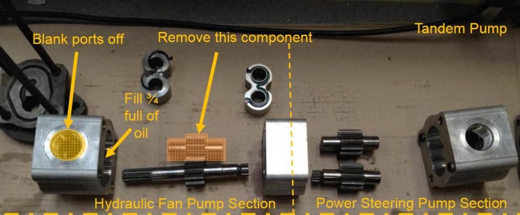
Some of these vehicles have what is termed a “Tandem Pump” this drive the fan AND the power steering… we are getting our trousers taken (metaphorically) down over the price of a single pump conversion… soooooooooo
We got to thinking, if we throw away the roundy roundy bit of the fan pump that will stop it working as a pump yet leave it working as a rather sophisticated driveshaft, blanking the ports off and filling it 3/4 full of oil of course then to our way of thinking this should retain the power steering pump as a fully functional unit.

Taking the laws of physics into account and our electrical expertise we likened this to effectively removing the stator from a generator AND running it off load. I’m sure this fill the criteria of the laws of physics BUT BUT BUT have we done enough to appease the gods of hydraulics???
MrOvershootFull MemberPosted 9 years agoNow bearing in mind I can’t see the picture “blocked at work” are you saying what you effectivly have is a twin chamber hydraulic pump, pump 1 powers the fan & pump 2 the power steering?
If so then blocking the ports on pump 1 will cause load so you would be better to pipe inlet and outlet together just circulating oil under very little pressurejock-muttleyFull MemberPosted 9 years agoMrO,
Exactly the arrangement we have but what we are saying is remove the Driven gear thus removing any pressure from the system effectively leaving the driving gear sitting in an oil bath as a “posh” driveshaft to the power steering part of the pump.
If that makes sense
 MrOvershootFull MemberPosted 9 years ago
It makes sense, I now get what you mean about 3/4 full. just to lubricate things, until I see the picture I can’t tell for sure.
My real area of stuff is electro/pneumatics but I get my hands covered in hydraulic fluid now and again 😉
I agree with you on the price of some hydraulic stuff it makes XTR level kit look like value baked beansmaxtorqueFull MemberPosted 9 years agoBe a little be careful. Generally speaking, pumps like that use deliberate “leakage” paths from the pressure gears to ensure a suitable feed of oil is maintained to the shaft bearings. In effect, some oil is allowed to get squeezed out sideways from the pump gears and into the bearing area of the shaft / housing. If you either run the pump with no load (no pressure) or remove the “idler” gear, you could run into issues with bearing failure.
Now, it depends a lot upon the radial load on the shafts, what sort of drive system is used (belts or gear drive to the nose of the pump puts on a lot of radial load etc) and on things like the internal system pressure.
So, yes, i’m sure removing the idle gear will work, but you may well want to try it first on a “pet” customers engine and inspect the pump regularly for shaft wear before rolling it out to others!
maxtorqueFull MemberPosted 9 years agoETA: in the picture, on the iron front housing you can see a machined “scroll” that is designed to feed the front bearing with oil under pressure to maintain the lubrication film. You may loose this = bad!
maxtorqueFull MemberPosted 9 years agoETA2: Looking at the housing, there is enough space to machine a pocket and insert a suitable ball bearing in there, which will probably avoid the issue, and only require “splash” feeding with oil etc
MrOvershootFull MemberPosted 9 years agoNow I’ve seen the picture I still think your easiest & cheapest option is to loop plumb the inlet & outlet of pump 1 together using a small bore hydraulic hose, this should give you a bit of back pressure so the bearings will get the required bypass lubrication without creating too much drag.
jock-muttleyFull MemberPosted 9 years agoYip, these look like pressure fed bearings, negligible radial load though, driven direct from engine.
The roller bearing solution looks good, we were thinking every permutation of not trying to do this, even wondering would it be possible to put a pressurised oil gallery into the “transfer block” and a unpressurized return, we do after all have a pump, but thinking about it the roller bearing route is simpler, unless you have a better suggestion.
DawnrazorFree MemberPosted 9 years agoI’m curious as to why the hydraulic fan is being replaced but that’s another matter. For me there are two options. (I) speak to the pump manufacturer or distributor and tell them what you are trying to do. Most of them are pretty good and will be happy to assist. (ii) keep the pump as it was and instead of running the pressurised output to the fan, instead take it to tank. If the hoses are sized correctly the losses will be negligible. Off the back of this you could run this oil through a low pressure filter creating a kidney loop to keep the oil nice and clean. Hope this helps.
jock-muttleyFull MemberPosted 9 years agoPump Manufacturer / Distributor is the issue, we are in a single source of supply situation and he not only has us over a barrel and with a gun to our head and is @rseraping us on price – AND his solution isn’t that brilliant as it adds additional cost as we have to mod the pipework to suit.
Hydraulic fan is being replaced because they are horrendously inefficient and unreliable when compared to the alternatives. This is us http://avidtp.com/ and no we aren’t “that” Avid…. lol
We are trying to bring this work in house, where we simply convert customers kit on a service exchange basis. Looks like we are going to run with MaxTorque’s recommendation an use needle roller bearings, it means a bit of machining work but we have a brilliant local machine shop to do that for use.
We just need to get a prototype built and tested to prove the theory.
Thanks chaps
maxtorqueFull MemberPosted 9 years agoNeedles are probably not the correct choice! Without the front element pumping you will have removed most of the radial loads when you removed the idler pump gear. With insufficient radial loads, needle rollers can slip, which is not good. I’d go for a low anglular contact ball bearing myself!
(the major bearing manufacturers and stockists will be happy to advise, but ask for datasheets and parameters for your chosen bearing, and check things like max loading / misalignment and speeds etc!)
maxtorqueFull MemberPosted 9 years agoBTW, interesting web site 😉
Do you do autodetection of blocked rad/fan packs and how do you find those WP29s?
(i find the new VDO/Conti gen3 pump to be significantly better)

The topic ‘Any Hydraulic Engineers? – (Grease Monkey content)’ is closed to new replies.